ESP32 Fall-Detection Learning Prototype · kit manualBack to the kit
DIYKITKit manual
Learn · Build · Make
ESP32 Fall-Detection Learning Prototype
5 lessons · Intermediate · 45-60 min setup, then 5 lessons of 25-60 min (about 4 hours in all)
Scan for code, photos & updates diykit.ae/kits/esp32-fall-detection-learning-prototype
An ESP32 learning kit about motion sensing: Start here, then 5 lessons - a button and OLED countdown, tilt angles from a GY-521 motion sensor, a live graph of jolts and drops, a buzzer alert, and finally a fall-detection experiment that starts a cancellable countdown when a jolt is followed by staying tipped over. Each lesson has a wiring diagram, code and troubleshooting. Code compiler-checked for the ESP32; the physical build is not bench-tested. A learning experiment only - not a medical, wheelchair-safety or emergency device.
Read before you build. Learning experiment only - not a medical device, wheelchair safety system, emergency alarm or substitute for supervision. It sends no message and calls no one. Never attach it to a person or a wheelchair. Test only on a light, padded, unoccupied platform; never drop or tip a person or a wheelchair. False alarms and missed events are expected - recording them is part of the lessons. Power the ESP32 from USB only. Do not connect a battery or charger to it. Every module (OLED, GY-521, buzzer) goes to 3V3 - never 5V or VIN. The buzzer module is powered from 3V3 so the ESP32 can switch it. Unplug USB before rewiring. Keep the buzzer away from ears. Code compiler-checked for the ESP32; the complete physical build, thresholds and detection are not bench-tested. Go by the labels printed on your parts. Recommended age: 12+ with adult supervision; adult help is required for any soldering.
What's in the box Tick each part as you unpack
1×ESP32U DevKitC Type-C ESP32U DevKitC board: a metal-covered ESP32 chip, two rows of pins, a USB-C socket and two small buttons (EN and BOOT).
1×GY-521 MPU-6050 6DOF IMU Sensor Module Small blue board marked GY-521 with 8 pins: VCC, GND, SCL, SDA, XDA, XCL, AD0, INT. Its pins may need soldering.
1×0.96" OLED Display Module 128x64 I2C (White) Small display with a glass screen and 4 pins labelled GND, VCC, SCL and SDA (the order varies).
1×Tactile Microswitch Kit 25pcs 12x12x7.3mm Momentary Push Button Switches with Assorted Coloured Caps Box of 25 square push buttons (12 × 12 mm) with coloured caps. Each has 4 legs. The lessons use one.
1×Jumper Wire Assorted Pack 120 Pieces Rainbow ribbons of 10 cm jumper wires: male-male, male-female and female-female.
1×Transparent 830 Points Solderless Breadboard Clear Prototype Circuit Board MB-102 High Quality DIY Electronic Testing Experiment PCB Base with Power Plane Clear 830-hole breadboard with red and blue lines along the edges.
1×Active Buzzer Module 5V DC (optional) Optional add-on: a small board with a round black buzzer and 3 pins (VCC, GND, I/O). Only if you added it to your order.
DIYKITESP32 Fall-Detection Learning Prototype · how to build this kit
How to build this kit Do these in order
1Check the box7 items. Tick each one off.Front page · What's in the box
2Get what is not in the box7 things to have ready, like a computer.This page · You also need
3Start here7 steps: set up the computer and upload Blink.Section 0 · Start here
4Do the lessons in order5, each with a diagram, steps, code and a fix-it table.Sections 1-5
5Stuck?Find what you see in the fault finder, then message us.Back pages · Fault finder, Stuck?
You also need not in the box
Item
For
Note
A computer (Windows, macOS or Linux) where you can install the free Arduino IDE 2 and the ESP32 tools
All lessons
A USB-C data cable - not a charge-only cable
All lessons
The ESP32U has a USB-C socket
An internet connection, for the IDE, the ESP32 tools and the libraries
Start here, Lesson 1
A small light box or book, and tape, as a test platform
Lessons 2, 3 and 5
A cushion or foam pad
Lessons 3 and 5
Tests only on a padded, unoccupied platform
Soldering, by an adult
Only if the GY-521 or OLED pins arrive loose
Adult only
A multimeter
Optional
No lesson needs one. Useful for an adult checking 3.3 V and GND.
Your learning path
00Start here - set up and upload Blink
01Lesson 1: Button & OLED Countdown · 40 min
02Lesson 2: Tilt Angle from a Baseline · 30 min
03Lesson 3: Motion Data Lab · 30 min
04Lesson 4: Buzzer Alert · 25 min
05Lesson 5: Fall-Detection Learning Prototype · 45-60 min
DIYKITESP32 Fall-Detection Learning Prototype · your progress
Your progress Tick each step when it works
#
Step and what you should see
Done
Date
1
Start here: install the Arduino IDE and the ESP32 tools, select ESP32 Dev Module and your port, and upload GetChipID - the chip model appears in the Serial Monitor.
2
Lesson 1 - Button & OLED Countdown (40 min): install Adafruit SSD1306; a button starts and cancels a 20-second countdown on the OLED.
3
Lesson 2 - Tilt Angle from a Baseline (30 min): the GY-521 learns "upright"; the OLED shows the tilt angle and flags 55°.
4
Lesson 3 - Motion Data Lab (30 min): total g on the Serial Plotter; impacts above 2.5 g and free falls below 0.45 g counted.
5
Lesson 4 - Buzzer Alert (25 min): buzzer on GPIO27, powered from 3V3; an alert the button acknowledges, with a 15-second time-out.
Kit pageCode to copy or download, full-size diagrams, photos and updates.diykit.ae/kits/esp32-fall-detection-learning-prototype
SimulatorRun each lesson's code on screen before you wire it. No hardware needed.diykit.ae/kits/esp32-fall-detection-learning-prototype/simulator
Help on WhatsAppOpens WhatsApp with the help message ready to fill in.+971 50 125 3600
What the simulator does not show. It is a good first check of your code, but the real parts behave a little differently:
The simulator checks your code and pins, not your wiring: it does not know whether a module is on 3V3 or 5V, or which button legs you used.
The tilt and g sliders give perfectly clean numbers. A real GY-521 is noisy, and real knocks and drops are much messier.
The buzzer is shown switching on and off. The simulator cannot tell how loud your module is at 3.3 V.
The simulator needs no ESP32 tools or libraries installed - the real Arduino IDE does (Start here and Lesson 1).
DIYKITESP32 Fall-Detection Learning Prototype · before you build
Before you build Read once, come back any time
How the breadboard connects
Each short row of 5 holes is joined inside the board. Two legs in the same row are connected; legs in different rows are not.
The gap down the middle splits every row in two: the 5 holes on the left are not joined to the 5 on the right.
The long lines of holes along the edges are the rails. In this kit the one by the red line is + (3.3 V from 3V3) and the one by the blue line is − (GND).
Long breadboards often split the rails halfway. If a part at the far end gets no power, add a short wire across the split.
Where the ESP32 goes
The ESP32 is too wide to sit on the breadboard and still leave free holes on both sides. Put it next to the breadboard.
Connect its pins with female-to-male jumper wires: the female end on the ESP32 pin, the male end in the breadboard.
Find each pin by the label printed next to it (3V3, GND, 21, 22, 26, 27), not by counting - different ESP32 boards put them in different places.
Reading the lesson diagrams
The ESP32 is drawn with only the pins each lesson uses, by their printed labels - not in their real positions.
The thick red line is the + rail (3.3 V) and the thick blue line is the − rail (GND). A wire that ends on a rail with a dot connects to that rail.
A dot means connected. Wires that cross without a dot do not touch.
The diagrams are drawn from the pin plan, not photographed from a tested build. The connection table under each one says the same thing in words.
Which way round
OLED, GY-521 and buzzer: go by the labels printed next to the pins. VCC goes to 3V3 and GND to GND - never swap them.
Push button: it has 4 legs in two joined pairs. Use two legs diagonally opposite each other - they are never joined inside, so the press always counts.
GY-521: only VCC, GND, SCL and SDA are used. Its 8 pins must be soldered on; loose pins pushed through the holes do not make contact.
Getting a lesson's code onto the ESP32
Scan the lesson's QR code. On the lesson page press Copy, or Download .ino.
In the Arduino IDE choose File → New Sketch, select everything, and paste the code over it.
Check the bottom of the window says ESP32 Dev Module and your port. Click Upload (→).
If it stops at "Connecting....", hold the BOOT button until the percentage starts.
Lessons 1-5 need the Adafruit SSD1306 library: Tools → Manage Libraries → Adafruit SSD1306 → Install → Install All (Lesson 1, step 1).
Serial Monitor and Serial Plotter
Every lesson prints to the computer. Open Tools → Serial Monitor (text) or Tools → Serial Plotter (a live graph).
Set the speed in the corner of the window to 115200 baud - every lesson in this kit uses 115200, the ESP32's normal speed.
Only one window can use the port at a time: close both before you upload.
DIYKITESP32 Fall-Detection Learning Prototype · pin plan
One pin plan for every lesson
Every lesson uses this one pin plan, so parts wired in one lesson stay where they are for the next. The numbers are the GPIO labels printed on the ESP32 - their position along the edge depends on the board version, so go by the labels.
ESP32 pin
Connects to
S
L1
L2
L3
L4
L5
Note
3V3
+ rail of the breadboard
●
●
●
●
●
Powers the OLED, GY-521 and buzzer. Never use 5V or VIN for them.
GND
− rail of the breadboard
●
●
●
●
●
Shared ground.
GPIO21
SDA: OLED and GY-521
●
●
●
●
●
I2C data - both modules share it.
GPIO22
SCL: OLED and GY-521
●
●
●
●
●
I2C clock - both modules share it.
GPIO26
Push button (other leg to GND)
●
●
●
●
●
INPUT_PULLUP - no resistor needed.
GPIO27
Buzzer I/O
●
●
Buzzer VCC goes to 3V3.
GPIO2
On-board LED, if your board has one
●
●
Nothing to wire. Some boards have no LED here.
GPIO6-11
Never use
Connected to the ESP32's flash memory.
GPIO0, GPIO12, GPIO15
Avoid
They decide how the ESP32 starts up.
GPIO4, 5, 13, 14, 16-19, 23, 25, 32, 33
Free
Spare pins for your own ideas. GPIO34-39 are inputs only.
S = Start here · L1-L5 = Lessons. The same pins are in every lesson's diagram and code.
DIYKITESP32 Fall-Detection Learning Prototype · start here
Start here
Follow these 7 steps before Lesson 1. They take about 45-60 minutes, most of it the one-time ESP32 download, and prove your computer, cable and ESP32 work - so if something goes wrong later, you know it is the wiring, not the setup.
0 · Start here45-60 min · setup
1 · Button & OLED Countdown40 min
2 · Tilt Angle from a Baseline30 min Adult help
3 · Motion Data Lab30 min Extra equipment
4 · Buzzer Alert25 min Extra equipment
5 · Fall-Detection Learning Prototype45-60 min Extra equipment
Lessons 1-4 need only the kit, a computer and a USB-C data cable. Lesson 4 needs the buzzer module, an optional add-on - without it, Lesson 5 still works, silently. Lessons 3 and 5 also need a cushion and a small box or book from home. Lesson 5 is an experiment on a padded bench - never on a person or a wheelchair.
Safety rules for every lesson.
This is a learning experiment, not a medical device, wheelchair safety system or emergency alarm. It sends no message and calls no one.
Never attach it to a person or a wheelchair. Test only on a light, padded, unoccupied platform.
Power the ESP32 from USB only. Do not connect batteries or chargers.
Every part in this kit goes to 3V3 - never to 5V or VIN.
Unplug the USB cable before you add, move or remove any wire.
Keep the buzzer away from your ears.
If anything gets hot or smells, or the ESP32 keeps restarting, unplug at once.
Small parts: keep them away from young children. Adult supervision for learners under 12.
DIYKITESP32 Fall-Detection Learning Prototype · start here
1Check the parts
Open the box and lay the parts out on a clear table.
Tick each one off against the photos and descriptions below.
Safety: Small parts: keep them away from young children and pets.
Use the "What's in the box" checklist on the front page.
You should see: You have the 6 items listed below - plus the buzzer module if you added it (it is optional).
Something is missing or broken
Send us a photo with your order number on WhatsApp.
Breadboard: A clear board full of holes that lets you connect parts without soldering.
2Check what else you need
Read the "You also need" list below.
Find a USB-C data cable for the ESP32, and a computer you are allowed to install software on.
See "You also need" on the "How to build this kit" page.
You should see: You have a computer, a USB-C data cable, an internet connection and an adult nearby.
3Install the Arduino IDE and the ESP32 tools
Download the free Arduino IDE 2 from arduino.cc/en/software and install it.
Open File → Preferences. In "Additional boards manager URLs" paste: https://espressif.github.io/arduino-esp32/package_esp32_index.json
Open Tools → Board → Boards Manager, search esp32 and install "esp32 by Espressif Systems". It is a big download - allow 10-20 minutes.
You should see: Tools → Board now has an "esp32" section.
The download or install is blocked
School and work computers often block installs. Ask an adult or use a home computer.
"esp32 by Espressif Systems" is not listed
Check the Preferences address is pasted exactly, then close and reopen the Boards Manager.
IDE: The program where you write code and send it to the board.
Core: The add-on that teaches the IDE about a type of board, here the ESP32.
4Connect the ESP32 with a USB-C data cable
Plug the cable into the ESP32 and the computer. Nothing else is connected yet.
Safety: Put the ESP32 on a dry table, away from coins, paper clips and other metal - they can touch the pins underneath and cause a short.
You should see: A small red power light on the ESP32 lights up.
No light at all
Push the plug fully in. Try another USB port, then another cable.
5Select the board and the port
Open Tools → Board → esp32 → ESP32 Dev Module.
Open Tools → Port and choose your ESP32: COM3, COM4… on Windows, /dev/cu.usbserial… or /dev/cu.SLAB… on a Mac, /dev/ttyUSB0 on Linux.
Not sure which one? Unplug the ESP32, look at the list, plug it back in: the new entry is yours.
You should see: The bottom of the IDE window shows "ESP32 Dev Module" and your port.
The Port menu is empty
Many USB cables only charge. Use a data cable.
Windows shows an unknown device
Look at the small chip next to the USB socket: CP2102 or CH340. The computer needs the free driver for that chip - ask us on WhatsApp for the link.
Linux: "permission denied" on the port
Ask an adult to add your user to the dialout group (sudo usermod -a -G dialout $USER), then log out and back in.
Port: The name your computer gives the USB connection to the board.
6Upload a first test
Open File → Examples → ESP32 → ChipID → GetChipID.
Click Upload (→) and wait for "Hard resetting via RTS pin..." or "Done uploading".
Open Tools → Serial Monitor and set the speed to 115200 baud.
You should see: Every 3 seconds the Serial Monitor prints the chip model (ESP32-D0WD…), its revision and the number of cores.
Try it: Change delay(3000) to delay(1000) and upload again. The lines appear every second. Now you know you can change code and upload it.
The upload stops at "Connecting....____"
Hold down the BOOT button on the ESP32 when "Connecting" appears, and let go when the percentage starts.
"Failed to connect" or "port is busy"
Close the Serial Monitor and any other program using the port, choose the port again (step 5) and retry.
A red "Compilation error"
Check Tools → Board is ESP32 Dev Module. Close the example without saving and open it again.
The Serial Monitor shows strange symbols
Set the speed to 115200 baud. Press the EN (reset) button to start the sketch again.
Upload: Sending your sketch from the computer into the board. It stays there after you unplug.
Serial Monitor: A window in the IDE (Tools → Serial Monitor) that shows the text the board sends.
7Continue to Lesson 1
Unplug the USB cable.
Open Lesson 1: Button & OLED Countdown and follow it step by step.
Do the lessons in order: each one builds on the last, and the wiring stays in place.
You should see: You are ready to build.
DIYKITESP32 Fall-Detection Learning Prototype · lesson 1 of 5
Lesson 1 · Basics
Lesson 1: Button & OLED Countdown
Beginner · 40 min
Wire the OLED screen and a button, then make a 20-second countdown that a press starts and a second press cancels.
Code & parts
Time40 min
Do these firstStart here: the ESP32 core installed and GetChipID uploaded
On your ownYou can do this lesson on your own once Start here is done. An adult nearby is a good idea for your first wiring.
Pins used3V3 + rail of the breadboardGND − rail of the breadboardGPIO21 SDA: OLED and GY-521GPIO22 SCL: OLED and GY-521GPIO26 Push button (other leg to GND)GPIO2 On-board LED, if your board has one
You will learn
Installing a library: Adafruit SSD1306
I2C: one pair of wires (SDA, SCL) for a whole screen
Reading a button with INPUT_PULLUP and debouncing it
Timing with millis() instead of delay()
Parts
ESP32U board + your USB-C data cable
1
830-point breadboard
1
0.96" OLED display
1
Push button (from the pack of 25)
1
Female-to-male jumper wires
about 6
Male-to-male jumper wires
about 4
How it works
The OLED has its own controller chip. The Adafruit SSD1306 library talks to it over I2C on GPIO21 (SDA) and GPIO22 (SCL), so the sketch only says what to draw.
INPUT_PULLUP holds GPIO26 HIGH. Pressing the button connects it to GND, so the pin reads LOW. That is why the button goes between GPIO26 and GND, with no resistor.
Metal contacts bounce for a few milliseconds. pressedNow() only believes a change that lasts 35 ms, so one press counts once.
The countdown never waits: each time round loop() it works out the seconds left from millis(), so the button is read all the time.
New words
3V3: The ESP32's 3.3 V power pin. Every part in this kit runs on 3.3 V.
GPIO: General-purpose input/output: a numbered pin the code can read or switch, such as GPIO26.
I2C: A way for chips to talk over two wires: SDA (data) and SCL (clock).
Pull-up: A built-in resistor that holds a pin HIGH until a button pulls it LOW.
Debounce: Ignoring the few milliseconds of flicker when a button's metal contacts touch.
Wiring
Connection diagram drawn from the pin plan - not a photo of a tested build. The table says the same in words.
Part / pin
Connect to
Note
ESP32 3V3
+ rail of the breadboard
NOT 5V or VIN - every part in this kit runs on 3.3 V
ESP32 GND
− rail of the breadboard
Shared ground for everything
OLED VCC
+ rail (3V3)
Go by the labels on the OLED - the pin order varies
OLED GND
− rail (GND)
OLED SDA
GPIO21
I2C data
OLED SCL
GPIO22
I2C clock
Button leg
GPIO26
Button leg diagonally opposite
− rail (GND)
Diagonal legs are never joined inside, so the press always counts
Step by step · tick each step as you finish it
Install the display library: in the Arduino IDE open Tools → Manage Libraries, search Adafruit SSD1306, click Install and choose Install All.
Unplug the USB cable.Watch out: Always unplug the USB cable before you add, move or remove a wire.
Put the ESP32 next to the breadboard, not on it. It is too wide to leave free holes on both sides. Use female-to-male jumper wires from its pins.Watch out: Put the ESP32 on a dry table, away from coins and other metal.
Find the pins labelled 3V3 and GND on the ESP32. Wire 3V3 to the + rail and GND to the − rail.Watch out: Use 3V3, never 5V or VIN, for the parts in this kit.
Push the OLED into the breadboard. Read its 4 labels, then wire VCC to the + rail, GND to the − rail, SDA to GPIO21 and SCL to GPIO22.Watch out: Go by the labels on your OLED. VCC and GND swapped can damage it.
Push one button across the middle gap of the breadboard. Wire one leg to GPIO26 and the leg diagonally opposite to the − rail.
Check every wire against the diagram and the table, then plug the USB cable back in.Watch out: If anything gets hot or smells, unplug straight away.
Copy the Lesson 1 code below into the Arduino IDE and click Upload (→). Open the Serial Monitor at 115200 baud.
Press the button: the countdown starts. Press again: it is cancelled. Let it run to 0 once.
The code · lesson1_button_countdown.ino
Easiest: scan the QR code above and press Copy or Download .ino on the lesson page, then paste it into the Arduino IDE and click Upload. The full listing is here for reading along.
/*
  DIY KIT - ESP32 Fall-Detection Learning Prototype
  Lesson 1 of 5: Button & OLED Countdown

  WIRING (unplug the USB cable before you wire)
    OLED  VCC -> 3V3    GND -> GND    SDA -> GPIO21    SCL -> GPIO22
    Push button: one leg -> GPIO26, the leg diagonally opposite -> GND
    (The ESP32's built-in pull-up keeps GPIO26 HIGH until you press.)

  WHAT SHOULD HAPPEN
    The OLED says "press to start". Press the button: a 20-second countdown
    runs in big numbers. Press again to cancel. If it reaches 0 the screen
    says EXPIRED - in Lesson 5 this is where the alert starts.
    Serial Monitor at 115200 baud shows the same messages.
*/

#include <Wire.h>
#include <Adafruit_GFX.h>
#include <Adafruit_SSD1306.h>

const int SDA_PIN = 21;
const int SCL_PIN = 22;
const int BUTTON_PIN = 26;
const int LED_PIN = 2;               // the small LED on many ESP32 boards; yours may not have one
const int COUNTDOWN_S = 20;          // seconds - try 5 while testing
const unsigned long DEBOUNCE_MS = 35;

Adafruit_SSD1306 display(128, 64, &Wire, -1);
bool displayOk = false;

bool counting = false;
unsigned long countdownStart = 0;
int lastShown = -1;
bool rawButton = HIGH, stableButton = HIGH;
unsigned long rawSince = 0;

// True once each time the button is pressed (not while it is held).
// A contact "bounces" for a few ms, so we wait DEBOUNCE_MS before believing it.
bool pressedNow() {
  bool reading = digitalRead(BUTTON_PIN);
  if (reading != rawButton) {
    rawButton = reading;
    rawSince = millis();
  }
  if (millis() - rawSince > DEBOUNCE_MS && reading != stableButton) {
    stableButton = reading;
    return stableButton == LOW;      // pull-up: LOW means pressed
  }
  return false;
}

// Most of these displays answer at I2C address 0x3C, some at 0x3D. Try both.
bool startDisplay() {
  if (display.begin(SSD1306_SWITCHCAPVCC, 0x3C)) { Serial.println("OLED found at 0x3C"); return true; }
  if (display.begin(SSD1306_SWITCHCAPVCC, 0x3D)) { Serial.println("OLED found at 0x3D"); return true; }
  Serial.println("OLED not found - unplug USB and check VCC, GND, SDA (GPIO21), SCL (GPIO22)");
  return false;
}

// Two lines of small text and, if seconds >= 0, a big number.
void show(const char *line1, const char *line2, int seconds) {
  if (!displayOk) return;
  display.clearDisplay();
  display.setTextColor(SSD1306_WHITE);
  display.setTextSize(1);
  display.setCursor(0, 0);
  display.println("COUNTDOWN LAB");
  display.println(line1);
  if (seconds >= 0) {
    display.setTextSize(3);
    display.setCursor(0, 22);
    display.println(seconds);
  }
  display.setTextSize(1);
  display.setCursor(0, 56);
  display.println(line2);
  display.display();                 // nothing appears until display() is called
}

void setup() {
  Serial.begin(115200);
  pinMode(BUTTON_PIN, INPUT_PULLUP);
  pinMode(LED_PIN, OUTPUT);
  Wire.begin(SDA_PIN, SCL_PIN);
  displayOk = startDisplay();
  show("ready", "press to start", -1);
  Serial.println("Lesson 1: press the button to start the countdown, press again to cancel");
}

void loop() {
  if (pressedNow()) {
    if (counting) {
      counting = false;
      Serial.println("CANCELLED");
      show("cancelled", "press to start", -1);
    } else {
      counting = true;
      countdownStart = millis();
      lastShown = -1;
      Serial.println("COUNTDOWN started");
    }
  }

  if (counting) {
    unsigned long used = millis() - countdownStart;
    int remaining = COUNTDOWN_S - (int)(used / 1000);
    unsigned long quarterSeconds = millis() / 250;
    digitalWrite(LED_PIN, quarterSeconds % 2 == 0 ? HIGH : LOW);   // blink while counting
    if (remaining <= 0) {
      counting = false;
      digitalWrite(LED_PIN, LOW);
      Serial.println("EXPIRED");
      show("EXPIRED", "press to start again", 0);
    } else if (remaining != lastShown) {
      lastShown = remaining;
      Serial.print("seconds left: ");
      Serial.println(remaining);
      show("counting down", "press to cancel", remaining);
    }
  } else {
    digitalWrite(LED_PIN, LOW);
  }
  delay(5);
}
How the code works
const int BUTTON_PIN = 26;
Names for the pins. If you move a wire, change only this number.
pinMode(BUTTON_PIN, INPUT_PULLUP);
Turns on the built-in pull-up: the pin reads HIGH until the button connects it to GND.
pressedNow()
Our own function: true once for each press, after the contact has been steady for 35 ms.
startDisplay()
Tries the OLED at address 0x3C, then 0x3D, and says which one answered.
COUNTDOWN_S - (used / 1000)
Seconds left, worked out from millis() - nothing waits.
Change it and see
Change: Change COUNTDOWN_S from 20 to 5. What happens: The countdown is over in 5 seconds - handy for testing.
Change: Change DEBOUNCE_MS from 35 to 0. What happens: Some presses may count twice: that is contact bounce.
What you should see or hear
The Serial Monitor says "OLED found at 0x3C" (or 0x3D) and the OLED says "press to start".
One press: the seconds count down in big numbers from 20. A second press: "cancelled".
At 0: "EXPIRED". If your board has a small LED on GPIO2, it blinks while counting.
If it doesn't work
"OLED not found" or a black screen
Unplug USB. Check OLED VCC to 3V3 (not 5V), GND, SDA to GPIO21 and SCL to GPIO22 - by the labels printed on the OLED.
The button does nothing
Unplug USB. Move one wire to the leg diagonally opposite: two legs on the same side can be joined inside the button.
The countdown starts by itself
GPIO26 is not wired to GND through the button, or a wire is loose. Check the button legs.
"Adafruit_SSD1306.h: No such file"
Install the library: step 1.
Nothing, or strange symbols, in the Serial Monitor
Set the speed in the corner of the Serial Monitor to 115200 baud.
The upload fails or stops at "Connecting..."
See Start here, step 6.
Small experiment
Hold the button down. Does the countdown start when you press, or when you let go? Look at pressedNow() and explain why.
Check what you learned
Why is no resistor needed for the button?
What does the pin read while the button is pressed?
Why use millis() instead of delay(20000)?
Answers: 1. INPUT_PULLUP turns on a resistor inside the ESP32. 2. LOW - the button connects it to GND. 3. delay() would freeze the program, so the button could not cancel the countdown.
In the simulator. In the simulator click the button to press it. The simulator does not need the Adafruit library installed - the real Arduino IDE does (step 1).
Next
Lesson 2 adds the GY-521 motion sensor on the same two I2C wires. Keep everything where it is.
My notes It worked Date: ____________ What I changed in the code, and what happened:
DIYKITESP32 Fall-Detection Learning Prototype · lesson 2 of 5
Lesson 2 · Sensing
Lesson 2: Tilt Angle from a Baseline
Beginner · 30 min
Add the motion sensor. It learns which way is "upright", then the OLED shows how many degrees you have tilted it.
Code & parts
Time30 min
Do these firstLesson 1
Adult help neededYou can do this lesson on your own.
Pins used3V3 + rail of the breadboardGND − rail of the breadboardGPIO21 SDA: OLED and GY-521GPIO22 SCL: OLED and GY-521GPIO26 Push button (other leg to GND)
You will learn
What an accelerometer measures: the pull of gravity, in g
Two I2C devices sharing the same two wires
Why "tilted" only means something compared with a starting position
Working out an angle between two directions
Parts
Wiring from Lesson 1
GY-521 (MPU-6050) motion sensor
1
Male-to-male jumper wires
4
How it works
Sitting still, the accelerometer feels only gravity: 1 g pointing down. Which of its x, y and z axes feel it tells us which way the sensor is facing.
For 3 seconds the sketch averages 150 readings while you keep it still. That direction becomes "upright", however the sensor is mounted.
After that it compares each new reading with "upright" and works out the angle between them (with acos of the dot product). 0° = as at the start, 90° = lying on its side.
The OLED and the GY-521 share SDA and SCL. They do not get mixed up because each has its own address.
New words
Accelerometer: A sensor that measures acceleration, including gravity, on three axes: x, y and z.
g: The pull of gravity. Sitting still, the sensor measures about 1 g in total.
Baseline: The starting position the sensor learns as "upright".
Address: The number an I2C device answers to: the GY-521 is 0x68 (or 0x69), the OLED 0x3C.
Wiring
Connection diagram drawn from the pin plan - not a photo of a tested build. The table says the same in words.
Part / pin
Connect to
Note
GY-521 VCC
+ rail (3V3)
GY-521 GND
− rail (GND)
GY-521 SDA
GPIO21
Same wire row as the OLED SDA
GY-521 SCL
GPIO22
Same wire row as the OLED SCL
GY-521 XDA, XCL, AD0, INT
Nothing
Leave empty
OLED, button
As in Lesson 1
GPIO21, GPIO22, GPIO26
Step by step · tick each step as you finish it
Unplug the USB cable.Watch out: Always unplug the USB cable before you add, move or remove a wire.
Check the GY-521 has its 8 header pins soldered on. If they are loose, stop: an adult must solder them first.Watch out: Soldering irons are very hot. Adults only.
Push the GY-521 into the breadboard. Wire VCC to the + rail (3V3), GND to the − rail, SDA into the same row as the OLED's SDA wire, SCL into the same row as the OLED's SCL wire.Watch out: VCC to 3V3, not 5V.
Leave XDA, XCL, AD0 and INT empty.
Tape the breadboard flat to a book or a piece of card, so the sensor cannot wobble.
Plug in USB, upload the Lesson 2 code and keep everything still for 3 seconds.
Tilt the book slowly. Watch the angle grow and "TILTED" appear past 55°. Press the button to learn a new "upright".
The code · lesson2_tilt_angle.ino
Easiest: scan the QR code above and press Copy or Download .ino on the lesson page, then paste it into the Arduino IDE and click Upload. The full listing is here for reading along.
/*
  DIY KIT - ESP32 Fall-Detection Learning Prototype
  Lesson 2 of 5: Tilt Angle from a Baseline

  WIRING (unplug the USB cable before you wire)
    Keep the OLED and button from Lesson 1.
    GY-521 (MPU-6050)  VCC -> 3V3   GND -> GND   SDA -> GPIO21   SCL -> GPIO22
    The OLED and the GY-521 share the same two I2C wires (SDA and SCL).
    Leave XDA, XCL, AD0 and INT on the GY-521 unconnected.

  WHAT SHOULD HAPPEN
    Keep the sensor still for 3 seconds while it learns "upright". Then the
    OLED shows the angle you have tilted it from that position. Past 55
    degrees it says TILTED. Press the button to learn a new "upright".
    Serial Monitor (115200) or Serial Plotter shows angle_deg.
*/

#include <Wire.h>
#include <Adafruit_GFX.h>
#include <Adafruit_SSD1306.h>

const int SDA_PIN = 21;
const int SCL_PIN = 22;
const int BUTTON_PIN = 26;
const float TILT_DEG = 55.0;          // the "lying down" angle used in Lesson 5
const int CALIBRATION_SAMPLES = 150;  // 150 x 20 ms = 3 seconds
const unsigned long SAMPLE_MS = 20;
const unsigned long REPORT_MS = 250;

Adafruit_SSD1306 display(128, 64, &Wire, -1);
bool displayOk = false;
int mpuAddress = 0;                   // 0x68 or 0x69, found at start
float baseX = 0, baseY = 0, baseZ = 1;  // the "upright" direction of gravity
unsigned long lastSample = 0, lastReport = 0;
bool lastButton = HIGH;

bool answers(int address) {
  Wire.beginTransmission(address);
  return Wire.endTransmission() == 0;
}

// Read the three accelerometer axes, in g. 1 g = the pull of gravity.
bool readAccel(float &x, float &y, float &z) {
  Wire.beginTransmission(mpuAddress);
  Wire.write(0x3B);                   // the first acceleration register
  if (Wire.endTransmission(false) != 0) return false;
  if (Wire.requestFrom(mpuAddress, 6) != 6) return false;
  int16_t rx = (int16_t)((Wire.read() << 8) | Wire.read());
  int16_t ry = (int16_t)((Wire.read() << 8) | Wire.read());
  int16_t rz = (int16_t)((Wire.read() << 8) | Wire.read());
  x = rx / 16384.0;                   // +-2 g range: 16384 counts per g
  y = ry / 16384.0;
  z = rz / 16384.0;
  return true;
}

void show(const char *line1, int angle) {
  if (!displayOk) return;
  display.clearDisplay();
  display.setTextColor(SSD1306_WHITE);
  display.setTextSize(1);
  display.setCursor(0, 0);
  display.println("TILT ANGLE LAB");
  display.println(line1);
  if (angle >= 0) {
    display.setTextSize(3);
    display.setCursor(0, 22);
    display.print(angle);
    display.setTextSize(2);
    display.print(" deg");
  }
  display.setTextSize(1);
  display.setCursor(0, 56);
  display.print("limit ");
  display.print((int)TILT_DEG);
  display.print("  btn=reset");      // "limit 55  btn=reset": 21 characters fit on a line
  display.display();
}

// Average 150 readings while the sensor is still: that is "upright".
bool calibrate() {
  show("KEEP STILL: 3 s", -1);
  Serial.println("Calibrating - keep the sensor still");
  float sx = 0, sy = 0, sz = 0;
  int good = 0;
  for (int i = 0; i < CALIBRATION_SAMPLES; i++) {
    float x, y, z;
    if (readAccel(x, y, z)) {
      sx += x; sy += y; sz += z;
      good++;
    }
    delay(SAMPLE_MS);
  }
  float length = sqrt(sx * sx + sy * sy + sz * sz);
  if (good == 0 || length < 0.001) return false;
  baseX = sx / length;                // keep only the direction
  baseY = sy / length;
  baseZ = sz / length;
  Serial.println("Calibrated");
  return true;
}

void setup() {
  Serial.begin(115200);
  pinMode(BUTTON_PIN, INPUT_PULLUP);
  Wire.begin(SDA_PIN, SCL_PIN);
  displayOk = display.begin(SSD1306_SWITCHCAPVCC, 0x3C) || display.begin(SSD1306_SWITCHCAPVCC, 0x3D);
  if (!displayOk) Serial.println("OLED not found - see Lesson 1");

  if (answers(0x68)) mpuAddress = 0x68;
  else if (answers(0x69)) mpuAddress = 0x69;
  if (mpuAddress == 0) {
    Serial.println("GY-521 not found - unplug USB and check VCC 3V3, GND, SDA GPIO21, SCL GPIO22");
    show("GY-521 NOT FOUND", -1);
    while (true) delay(1000);         // stop here
  }
  Serial.print("GY-521 found at 0x");
  Serial.println(mpuAddress, HEX);
  Wire.beginTransmission(mpuAddress); // wake the sensor up (it starts asleep)
  Wire.write(0x6B);
  Wire.write(0x00);
  Wire.endTransmission();
  delay(50);
  if (!calibrate()) Serial.println("Calibration failed - is the sensor wired?");
}

void loop() {
  bool button = digitalRead(BUTTON_PIN);
  if (button == LOW && lastButton == HIGH) calibrate();   // press: learn a new "upright"
  lastButton = button;

  if (millis() - lastSample < SAMPLE_MS) return;
  lastSample = millis();
  float x, y, z;
  if (!readAccel(x, y, z)) return;
  float length = sqrt(x * x + y * y + z * z);
  if (length < 0.001) return;

  // The angle between "upright" and gravity now: the dot product of the two directions.
  float dot = (x * baseX + y * baseY + z * baseZ) / length;
  float angle = acos(constrain(dot, -1.0, 1.0)) * 180.0 / PI;

  if (millis() - lastReport >= REPORT_MS) {
    lastReport = millis();
    Serial.print("angle_deg:");
    Serial.print(angle, 1);
    Serial.print(",limit:");
    Serial.println(TILT_DEG, 0);
    show(angle >= TILT_DEG ? "TILTED past the limit" : "upright", (int)angle);
  }
}
How the code works
readAccel(x, y, z)
Reads the 6 bytes of acceleration from the GY-521 over I2C and turns them into g.
calibrate()
Averages 150 readings and keeps only the direction: the "upright" baseline.
acos(dot) * 180 / PI
The angle between "upright" and gravity now, in degrees.
answers(0x68)
Asks "is anyone at address 0x68?" - that is how the sketch finds the sensor.
Change it and see
Change: Change TILT_DEG from 55 to 30. What happens: "TILTED" appears much sooner.
Change: Calibrate with the book on its side (press the button), then lay it flat. What happens: Flat now reads about 90°: the angle is always from the baseline.
What you should see or hear
"GY-521 found at 0x68", then "KEEP STILL" for 3 seconds.
Flat and still: 0-2°. Tilted: the angle on the OLED follows you.
Past 55°: "TILTED past the limit". The Serial Plotter shows angle_deg and the limit line.
If it doesn't work
"GY-521 not found"
Unplug USB. Check VCC to 3V3, GND, SDA to GPIO21 and SCL to GPIO22. Are the GY-521 header pins soldered? Loose pins pushed through the holes do not make contact.
The angle never comes back to 0
It moved during the 3 seconds. Press the button and keep still.
The angle jumps about
Tape the sensor down firmly - a loose sensor wobbles.
"OLED not found" or a black screen
Unplug USB. Check OLED VCC to 3V3 (not 5V), GND, SDA to GPIO21 and SCL to GPIO22 - by the labels printed on the OLED.
Nothing, or strange symbols, in the Serial Monitor
Set the speed in the corner of the Serial Monitor to 115200 baud.
Small experiment
Calibrate, then turn the book upside down. What angle does it show? Why is 180° the biggest angle you can get?
Check what you learned
What does the accelerometer measure when it is sitting still?
Why does the sketch learn a baseline instead of using "flat"?
How can two devices share SDA and SCL?
Answers: 1. Gravity: about 1 g. 2. So the angle is right however the sensor is mounted. 3. Each has its own I2C address.
In the simulator. In the simulator the tilt slider sets the angle directly, so the numbers are perfectly steady. A real sensor wobbles by a degree or two.
Next
Lesson 3 measures jolts and drops instead of slow tilts.
My notes It worked Date: ____________ What I changed in the code, and what happened:
DIYKITESP32 Fall-Detection Learning Prototype · lesson 3 of 5
Lesson 3 · Sensing
Lesson 3: Motion Data Lab
Intermediate · 30 min
Draw the total g-force on a live graph and count every jolt and every drop - the two signals the main build looks for.
Code & parts
Time30 min
Do these firstLesson 2
On your ownYou can do this lesson on your own. Use a padded, unoccupied test platform - never a person. Not in the boxA cushion or foam pad to drop the test platform onto (yours)
Pins used3V3 + rail of the breadboardGND − rail of the breadboardGPIO21 SDA: OLED and GY-521GPIO22 SCL: OLED and GY-521GPIO26 Push button (other leg to GND)
You will learn
Free fall reads near 0 g; a landing spikes above 2 g
Counting a crossing once, not every reading above a line
Choosing limits (thresholds) from measurements
Live graphs in the Serial Plotter
Parts
Wiring from Lesson 2 - nothing new
A book or card with the breadboard taped on, and a cushion (yours)
How it works
The sketch combines x, y and z into one number, the total g: about 1.0 when still, whichever way the sensor faces.
It sets the sensor to ±8 g so a hard landing does not go off the scale (Lesson 2 used ±2 g for finer angles).
A crossing is counted once: only when total g goes above 2.5 g (or below 0.45 g) after being on the other side.
The Serial Plotter draws total_g with the two limits as flat lines, so you can see how close each movement gets.
New words
Free fall: Falling freely: the sensor feels almost no force, so total g drops towards 0.
Impact: A sudden stop: total g spikes far above 1.
Threshold: A limit, such as 2.5 g, where the behaviour changes.
Serial Plotter: Tools → Serial Plotter: draws the numbers the board sends as moving lines.
Wiring
Connection diagram drawn from the pin plan - not a photo of a tested build. The table says the same in words.
Part / pin
Connect to
Note
No changes
Same as Lesson 2
GY-521 and OLED on GPIO21/22, button on GPIO26
Step by step · tick each step as you finish it
Upload the Lesson 3 code. No wiring changes are needed.
Close the Serial Monitor, then open Tools → Serial Plotter at 115200 baud.Watch out: Only one of the two can be open at a time.
With the platform still on the table, total_g sits near 1.0.
Lift the platform 10 cm above a cushion and let go. Watch the dip and the spike.Watch out: Keep the USB cable slack and the drop short. Use only a padded, unoccupied platform - never a person.
Try gentle bumps, a tap on the table and a slow tilt. Which ones cross the lines? Press the button to reset the counts between tests.
The code · lesson3_motion_data.ino
Easiest: scan the QR code above and press Copy or Download .ino on the lesson page, then paste it into the Arduino IDE and click Upload. The full listing is here for reading along.
/*
  DIY KIT - ESP32 Fall-Detection Learning Prototype
  Lesson 3 of 5: Motion Data Lab

  WIRING: the same as Lesson 2 (OLED and GY-521 on GPIO21/22, button on GPIO26).

  WHAT SHOULD HAPPEN
    Open Tools > Serial Plotter at 115200 baud. The total_g line sits at about
    1.0 while the sensor is still. Lift and drop the test platform gently onto
    foam: total_g dips towards 0 while it falls and spikes when it lands.
    The OLED counts every IMPACT (above 2.5 g) and FREE FALL (below 0.45 g).
    Press the button to set the counts back to 0.
    Use a padded, unoccupied test platform - never a person.
*/

#include <Wire.h>
#include <Adafruit_GFX.h>
#include <Adafruit_SSD1306.h>

const int SDA_PIN = 21;
const int SCL_PIN = 22;
const int BUTTON_PIN = 26;
const float IMPACT_G = 2.5;           // the same limits as Lesson 5
const float FREEFALL_G = 0.45;
const unsigned long SAMPLE_MS = 20;   // 50 readings a second
const unsigned long REPORT_MS = 100;  // 10 plotter points a second

Adafruit_SSD1306 display(128, 64, &Wire, -1);
bool displayOk = false;
int mpuAddress = 0;
int impacts = 0, freefalls = 0;
bool wasImpact = false, wasFreefall = false;
float peakG = 0, lowestG = 10;
unsigned long lastSample = 0, lastReport = 0;
bool lastButton = HIGH;

bool answers(int address) {
  Wire.beginTransmission(address);
  return Wire.endTransmission() == 0;
}

bool writeRegister(int reg, int value) {
  Wire.beginTransmission(mpuAddress);
  Wire.write(reg);
  Wire.write(value);
  return Wire.endTransmission() == 0;
}

bool readAccel(float &x, float &y, float &z) {
  Wire.beginTransmission(mpuAddress);
  Wire.write(0x3B);
  if (Wire.endTransmission(false) != 0) return false;
  if (Wire.requestFrom(mpuAddress, 6) != 6) return false;
  int16_t rx = (int16_t)((Wire.read() << 8) | Wire.read());
  int16_t ry = (int16_t)((Wire.read() << 8) | Wire.read());
  int16_t rz = (int16_t)((Wire.read() << 8) | Wire.read());
  x = rx / 4096.0;                    // +-8 g range: 4096 counts per g
  y = ry / 4096.0;
  z = rz / 4096.0;
  return true;
}

void showCounts(float g) {
  if (!displayOk) return;
  display.clearDisplay();
  display.setTextColor(SSD1306_WHITE);
  display.setTextSize(1);
  display.setCursor(0, 0);
  display.println("MOTION DATA LAB");
  display.setTextSize(2);
  display.setCursor(0, 12);
  display.print(g, 2);
  display.println(" g");
  display.setTextSize(1);
  display.setCursor(0, 34);
  display.print("impacts   "); display.println(impacts);
  display.print("free falls "); display.println(freefalls);
  display.print("peak "); display.print(peakG, 1); display.print("  low "); display.println(lowestG, 2);
  display.display();
}

void setup() {
  Serial.begin(115200);
  pinMode(BUTTON_PIN, INPUT_PULLUP);
  Wire.begin(SDA_PIN, SCL_PIN);
  displayOk = display.begin(SSD1306_SWITCHCAPVCC, 0x3C) || display.begin(SSD1306_SWITCHCAPVCC, 0x3D);
  if (answers(0x68)) mpuAddress = 0x68;
  else if (answers(0x69)) mpuAddress = 0x69;
  if (mpuAddress == 0 || !writeRegister(0x6B, 0x00) || !writeRegister(0x1C, 0x10)) {   // wake up, +-8 g
    Serial.println("GY-521 not found - see Lesson 2");
    while (true) delay(1000);
  }
  Serial.println("Lesson 3: open the Serial Plotter");
}

void loop() {
  bool button = digitalRead(BUTTON_PIN);
  if (button == LOW && lastButton == HIGH) {   // press: reset the counts
    impacts = 0; freefalls = 0; peakG = 0; lowestG = 10;
  }
  lastButton = button;

  if (millis() - lastSample < SAMPLE_MS) return;
  lastSample = millis();
  float x, y, z;
  if (!readAccel(x, y, z)) return;
  float g = sqrt(x * x + y * y + z * z);   // total g-force, whichever way it points
  if (g > peakG) peakG = g;
  if (g < lowestG) lowestG = g;

  // Count each crossing once, not every reading above the line.
  bool impact = g > IMPACT_G;
  if (impact && !wasImpact) impacts++;
  wasImpact = impact;
  bool freefall = g < FREEFALL_G;
  if (freefall && !wasFreefall) freefalls++;
  wasFreefall = freefall;

  if (millis() - lastReport >= REPORT_MS) {
    lastReport = millis();
    Serial.print("total_g:");
    Serial.print(g, 2);
    Serial.print(",impact_line:");
    Serial.print(IMPACT_G, 2);
    Serial.print(",freefall_line:");
    Serial.println(FREEFALL_G, 2);
    showCounts(g);
  }
}
How the code works
writeRegister(0x1C, 0x10)
Sets the sensor's range to ±8 g: 4096 counts per g.
sqrt(x*x + y*y + z*z)
The total g-force, whichever way the sensor points.
if (impact && !wasImpact) impacts++;
Counts a crossing only when it starts, not every reading above the line.
Serial.print("total_g:")
"name:value" pairs are what the Serial Plotter draws as labelled lines.
Change it and see
Change: Change IMPACT_G from 2.5 to 1.5. What happens: Small bumps now count as impacts too.
Change: Change REPORT_MS from 100 to 20. What happens: The graph shows every reading - short spikes are easier to see.
What you should see or hear
Still: total_g about 1.0, a flat line between the two limit lines.
A short drop onto a cushion: a dip towards 0 (free fall) then a spike (impact). The OLED counts each.
A slow tilt: total_g stays near 1.0 - tilting alone is not an impact.
If it doesn't work
"GY-521 not found"
Unplug USB. Check VCC to 3V3, GND, SDA to GPIO21 and SCL to GPIO22. Are the GY-521 header pins soldered? Loose pins pushed through the holes do not make contact.
The Plotter shows nothing
Close the Serial Monitor first, then open the Plotter at 115200 baud.
Nothing ever crosses the impact line
A soft cushion slows the landing. Try a firmer pad, or lower IMPACT_G to see the data.
Counts go up while it sits still
A loose wire or loose sensor. Tape everything down and check SDA and SCL.
Small experiment
Drop the platform 5 times from 10 cm and 5 times from 20 cm. Write down the peak g each time. Does a higher drop always give a bigger spike?
Check what you learned
What does total g read in free fall?
Why count only the start of a crossing?
Why is ±8 g used here instead of ±2 g?
Answers: 1. Close to 0. 2. Otherwise one impact lasting several readings would count many times. 3. A landing can go far above 2 g; ±8 g keeps it on the scale.
In the simulator. In the simulator the g slider sets total g directly - drag it above 2.5 or below 0.45 to see the counts change.
Next
Lesson 4 adds the buzzer so the alert can be heard.
My notes It worked Date: ____________ What I changed in the code, and what happened:
DIYKITESP32 Fall-Detection Learning Prototype · lesson 4 of 5
Lesson 4 · Basics
Lesson 4: Buzzer Alert
Beginner · 25 min
Add the buzzer and build an alert that beeps until you press the button - and stops by itself after 15 seconds.
Code & parts
Time25 min
Do these firstLesson 3
On your ownYou can do this lesson on your own. The buzzer module is an optional add-on: if your kit has no buzzer, read this lesson and go on to Lesson 5 - it works without sound. Not in the boxThe buzzer module (optional add-on)
Pins used3V3 + rail of the breadboardGND − rail of the breadboardGPIO21 SDA: OLED and GY-521GPIO22 SCL: OLED and GY-521GPIO26 Push button (other leg to GND)GPIO27 Buzzer I/O
You will learn
Wiring a 5 V module safely to a 3.3 V board
A beep pattern from millis() and the % (remainder) operator
Why every alarm needs a way to stop
Active-high and active-low outputs
Parts
Wiring from Lessons 1-3
Active buzzer module
1
Female-to-male jumper wires
3
How it works
The module has a small transistor that switches the buzzer. It is sold as a 5 V module, but here its VCC goes to 3V3: then the ESP32's 3.3 V signal can switch it fully on and off. The beep is quieter than at 5 V.
Powering it from 5V could leave it beeping all the time, because a 3.3 V signal may not be enough to switch a 5 V module off. That is why this kit uses 3V3.
used % 500 says where we are in each half-second: the first 150 ms are on, the other 350 ms off. The pattern repeats without any delay().
An alert that cannot be stopped is a problem too: the button acknowledges it, and after 15 seconds it stops by itself.
New words
Active buzzer: A buzzer with its own tone maker: switch its pin on and it beeps.
Acknowledge: Telling an alarm "I have seen it", which stops it.
Time-out: A limit after which something stops by itself.
% (remainder): What is left after dividing: 1300 % 500 = 300. It makes a pattern repeat.
Wiring
Connection diagram drawn from the pin plan - not a photo of a tested build. The table says the same in words.
Part / pin
Connect to
Note
Buzzer I/O (signal)
GPIO27
May be labelled S or IN
Buzzer VCC
+ rail (3V3)
Not 5V - see "How it works"
Buzzer GND
− rail (GND)
OLED, GY-521, button
As in Lessons 1-3
GPIO21, GPIO22, GPIO26
Step by step · tick each step as you finish it
Unplug the USB cable.Watch out: Always unplug the USB cable before you add, move or remove a wire.
Read the buzzer module's 3 labels: I/O (or S or IN), VCC and GND.Watch out: Go by the labels, not the position.
Wire I/O to GPIO27, VCC to the + rail (3V3) and GND to the − rail, using female-to-male jumpers.Watch out: VCC goes to 3V3, not 5V.
Plug in USB and upload the Lesson 4 code. Listen for 3 short test beeps.Watch out: Keep the buzzer away from your ears.
Press the button: ALERT, beeping. Press again: stopped. Start one more and wait 15 seconds without pressing.
The code · lesson4_buzzer_alert.ino
Easiest: scan the QR code above and press Copy or Download .ino on the lesson page, then paste it into the Arduino IDE and click Upload. The full listing is here for reading along.
/*
  DIY KIT - ESP32 Fall-Detection Learning Prototype
  Lesson 4 of 5: Buzzer Alert

  WIRING (unplug the USB cable before you wire)
    Keep everything from Lessons 1-3.
    Active buzzer module, with 3 female-to-male jumper wires:
      I/O (signal, may be labelled S or IN) -> GPIO27
      VCC                                   -> 3V3  (NOT 5V - see the lesson)
      GND                                   -> GND

  WHAT SHOULD HAPPEN
    Three short test beeps. Then press the button to start an ALERT: the
    buzzer beeps 150 ms on, 350 ms off and the OLED says ALERT. Press again
    to acknowledge (stop) it. If nobody presses, it stops by itself after
    15 seconds. Serial Monitor at 115200 baud.
*/

#include <Wire.h>
#include <Adafruit_GFX.h>
#include <Adafruit_SSD1306.h>

const int SDA_PIN = 21;
const int SCL_PIN = 22;
const int BUTTON_PIN = 26;
const int BUZZER_PIN = 27;
const unsigned long BEEP_ON_MS = 150;
const unsigned long BEEP_OFF_MS = 350;
const unsigned long MAX_ALERT_MS = 15000;   // an alarm must not run for ever
const unsigned long DEBOUNCE_MS = 35;

// Most modules beep when the pin is HIGH. If yours beeps in the gaps or
// all the time, change false to true and upload again.
const bool BUZZER_ACTIVE_LOW = false;

Adafruit_SSD1306 display(128, 64, &Wire, -1);
bool displayOk = false;
bool alerting = false;
unsigned long alertStart = 0;
bool rawButton = HIGH, stableButton = HIGH;
unsigned long rawSince = 0;

void buzzer(bool on) {
  if (BUZZER_ACTIVE_LOW) digitalWrite(BUZZER_PIN, on ? LOW : HIGH);
  else                   digitalWrite(BUZZER_PIN, on ? HIGH : LOW);
}

bool pressedNow() {
  bool reading = digitalRead(BUTTON_PIN);
  if (reading != rawButton) {
    rawButton = reading;
    rawSince = millis();
  }
  if (millis() - rawSince > DEBOUNCE_MS && reading != stableButton) {
    stableButton = reading;
    return stableButton == LOW;
  }
  return false;
}

void show(const char *line1, const char *line2) {
  if (!displayOk) return;
  display.clearDisplay();
  display.setTextColor(SSD1306_WHITE);
  display.setTextSize(1);
  display.setCursor(0, 0);
  display.println("BUZZER ALERT LAB");
  display.setTextSize(2);
  display.setCursor(0, 20);
  display.println(line1);
  display.setTextSize(1);
  display.setCursor(0, 56);
  display.println(line2);
  display.display();
}

void setup() {
  Serial.begin(115200);
  pinMode(BUTTON_PIN, INPUT_PULLUP);
  pinMode(BUZZER_PIN, OUTPUT);
  buzzer(false);
  Wire.begin(SDA_PIN, SCL_PIN);
  displayOk = display.begin(SSD1306_SWITCHCAPVCC, 0x3C) || display.begin(SSD1306_SWITCHCAPVCC, 0x3D);

  Serial.println("Lesson 4: three test beeps");
  for (int i = 0; i < 3; i++) {
    buzzer(true);  delay(100);
    buzzer(false); delay(200);
  }
  show("READY", "press to start alert");
  Serial.println("Press the button to start an alert, press again to stop it");
}

void loop() {
  bool pressed = pressedNow();
  unsigned long now = millis();

  if (!alerting) {
    if (pressed) {
      alerting = true;
      alertStart = now;
      Serial.println("ALERT started");
      show("ALERT", "press to acknowledge");
    }
  } else {
    unsigned long used = now - alertStart;
    if (pressed || used >= MAX_ALERT_MS) {
      alerting = false;
      buzzer(false);
      Serial.println(pressed ? "ACKNOWLEDGED" : "TIMED OUT after 15 s");
      show(pressed ? "STOPPED" : "TIMED OUT", "press to start alert");
    } else {
      // Where are we in one 500 ms beep cycle? The first 150 ms are "on".
      unsigned long phase = used % (BEEP_ON_MS + BEEP_OFF_MS);
      buzzer(phase < BEEP_ON_MS);
    }
  }
  delay(2);
}
How the code works
const int BUZZER_PIN = 27;
The buzzer's signal pin.
const bool BUZZER_ACTIVE_LOW = false;
Most modules beep when the pin is HIGH. If yours beeps in the gaps or all the time, change it to true.
used % (BEEP_ON_MS + BEEP_OFF_MS)
Where we are in each 500 ms cycle; under 150 means "beep".
MAX_ALERT_MS = 15000
The time-out: the alert stops by itself after 15 seconds.
Change it and see
Change: Change BEEP_OFF_MS from 350 to 100. What happens: A faster, more urgent pattern.
Change: Change MAX_ALERT_MS from 15000 to 5000. What happens: The alert gives up after 5 seconds.
What you should see or hear
Three short beeps at start, then "READY" on the OLED.
Press: "ALERT" and 2 beeps a second. Press again: "STOPPED" and silence.
Without a press, "TIMED OUT" after 15 seconds.
If it doesn't work
No sound at all
Unplug USB. Check I/O to GPIO27, VCC to 3V3 and GND, by the labels. Some 5 V modules are very quiet or silent at 3.3 V - tell us if yours is.
It beeps in the gaps, or all the time
Your module beeps when the pin is LOW. Set BUZZER_ACTIVE_LOW to true and upload again.
Only a click, no beep
It may be a passive buzzer. Check the label says active, or ask us.
"OLED not found" or a black screen
Unplug USB. Check OLED VCC to 3V3 (not 5V), GND, SDA to GPIO21 and SCL to GPIO22 - by the labels printed on the OLED.
The upload fails or stops at "Connecting..."
See Start here, step 6.
Small experiment
Time how long the alert runs before TIMED OUT with a stopwatch. Then change MAX_ALERT_MS and check again.
Check what you learned
Why is the buzzer powered from 3V3 and not 5V?
What is 1300 % 500?
Why does the alert have a time-out?
Answers: 1. So the ESP32's 3.3 V signal can switch it fully off; at 5V it might never stop. 2. 300. 3. An alarm that can never stop is a problem too - and the battery or the people nearby would suffer.
In the simulator. The simulator shows the buzzer pin switching on and off. It cannot tell how loud your module is at 3.3 V, or whether it beeps on HIGH or LOW.
Next
Lesson 5 puts it all together: the motion rule, the countdown, the button and the buzzer.
My notes It worked Date: ____________ What I changed in the code, and what happened:
DIYKITESP32 Fall-Detection Learning Prototype · lesson 5 of 5
Lesson 5 · Automation
Lesson 5: Fall-Detection Learning Prototype
Intermediate · 45-60 min
Put it all together: a jolt or drop followed by staying tipped over starts a beeping 20-second countdown that the button cancels. A learning experiment on the bench - not a safety device.
Code & parts
Time45-60 min
Do these firstLessons 1-4
On your ownYou can do this lesson on your own; an adult should check the test platform. Never attach the prototype to a person or a wheelchair. Not in the boxA small, light test platform (a box or book) and a cushion or foam pad (yours)
Pins used3V3 + rail of the breadboardGND − rail of the breadboardGPIO21 SDA: OLED and GY-521GPIO22 SCL: OLED and GY-521GPIO26 Push button (other leg to GND)GPIO27 Buzzer I/OGPIO2 On-board LED, if your board has one
You will learn
A state machine: MONITORING, candidate, COUNTDOWN, ALERT, FAULT
Why one reading is not enough: a jolt AND staying tipped over
Fault handling: stopping clearly when a sensor is missing
Testing honestly: recording false alarms and missed events
Parts
Everything from Lessons 1-4 (the buzzer only if you have it)
all
Light test platform and cushion (yours)
How it works
At start it finds one OLED and one GY-521, then learns "upright" for 3 seconds (Lesson 2). If anything is missing it shows FAULT and stops, rather than pretending to work.
MONITORING reads the sensor 50 times a second. A total above 2.5 g or below 0.45 g (Lesson 3) makes a candidate.
Within 5 seconds the platform must stay tipped more than 55° from upright for 1.5 seconds. Only then does the 20-second countdown start, beeping once a second.
A press cancels the countdown. If nobody presses, LOCAL ALERT beeps (Lesson 4; silent without the buzzer) until the button acknowledges it. Nothing is sent anywhere: no Wi-Fi, no message, no call.
New words
State machine: A program that is always in one named state and moves between them by rules.
Candidate: A possible event: a jolt or drop that might be a fall, waiting to be confirmed.
False alarm: An alert when nothing happened.
Missed event: Nothing happened on screen when it should have.
Wiring
Connection diagram drawn from the pin plan - not a photo of a tested build. The table says the same in words.
Part / pin
Connect to
Note
OLED and GY-521 VCC / GND
+ rail (3V3) / − rail
Lessons 1-2
OLED and GY-521 SDA / SCL
GPIO21 / GPIO22
Shared I2C
Button
GPIO26 and GND
Lesson 1
Buzzer I/O / VCC / GND
GPIO27 / 3V3 / GND
Lesson 4
On-board LED (if your board has one)
GPIO2
Nothing to wire
Step by step · tick each step as you finish it
Check all the wiring from Lessons 1-4 against the diagram.Watch out: Always unplug the USB cable before you add, move or remove a wire.
Tape the breadboard and the ESP32 to a light box or book: the test platform.Watch out: Never attach the prototype to a person or a wheelchair.
Plug in USB, upload the Lesson 5 code and keep the platform still and upright for 3 seconds: KEEP STILL, then MONITORING.
Test the button first: change FALL_DIAGNOSTIC to true, upload, and press the button - the countdown starts with beeps. Press again to cancel. Then set it back to false and upload again.
Over a cushion, give the platform a sharp knock and tip it onto its side. Hold it there for 2 seconds: POSSIBLE EVENT and beeps.Watch out: Short, gentle tests on a padded surface only.
Press the button to cancel. Then do it again and let the 20 seconds run out: LOCAL ALERT. Press to acknowledge.Watch out: Keep the buzzer away from your ears.
Try ordinary bumps, slow tilts and a knock without tipping over. Write down every false alarm and every missed event.
The code · lesson5_fall_detection.ino
Easiest: scan the QR code above and press Copy or Download .ino on the lesson page, then paste it into the Arduino IDE and click Upload. The full listing is here for reading along.
/*
  DIY KIT - ESP32 Fall-Detection Learning Prototype
  Lesson 5 of 5: Fall-Detection Learning Prototype (the main build)

  WIRING: everything from Lessons 1-4.
    OLED and GY-521: VCC -> 3V3, GND -> GND, SDA -> GPIO21, SCL -> GPIO22
    Button: GPIO26 and GND        Buzzer: I/O -> GPIO27, VCC -> 3V3, GND -> GND

  WHAT SHOULD HAPPEN
    KEEP STILL AND LEVEL for 3 seconds (it learns "upright"), then MONITORING.
    A jolt above 2.5 g or a drop below 0.45 g, followed by staying tipped more
    than 55 degrees for 1.5 seconds, starts a 20-second countdown with a beep
    every second. Press the button to cancel. If nobody does, LOCAL ALERT:
    the buzzer beeps until you press the button. Nothing is sent anywhere.
    Serial Monitor at 115200 baud.

    Set FALL_DIAGNOSTIC to true to start the countdown with the button
    instead of a movement - handy for testing the screen and buzzer.

  An educational bench prototype. NOT a medical, wheelchair, emergency or
  life-safety device. Test only on a padded, unoccupied platform.
*/

#include <Arduino.h>
#include <Wire.h>
#include <Adafruit_GFX.h>
#include <Adafruit_SSD1306.h>

#ifndef FALL_DIAGNOSTIC
#define FALL_DIAGNOSTIC false
#endif

constexpr uint8_t SDA_PIN = 21;
constexpr uint8_t SCL_PIN = 22;
constexpr uint8_t BUTTON_PIN = 26;
constexpr uint8_t BUZZER_PIN = 27;  // Lesson 4
constexpr uint8_t LED_PIN = 2;  // Common ESP32 Dev Module onboard LED; verify board.
// Most buzzer modules beep when the pin is HIGH. If yours beeps in the gaps
// or all the time, change false to true (see Lesson 4).
constexpr bool BUZZER_ACTIVE_LOW = false;
constexpr uint32_t SAMPLE_MS = 20;
constexpr uint32_t DEBOUNCE_MS = 35;
constexpr uint32_t CANDIDATE_MS = 5000;
constexpr uint32_t TILT_HOLD_MS = 1500;
constexpr uint32_t COUNTDOWN_MS = 20000;
constexpr uint32_t DISPLAY_MS = 250;
constexpr float IMPACT_G = 2.5f;
constexpr float FREEFALL_G = 0.45f;
constexpr float TILT_DEG = 55.0f;

Adafruit_SSD1306 display(128, 64, &Wire, -1, 100000, 100000);

enum class State { Monitoring, Candidate, Countdown, Alert, Fault };
State state = State::Fault;
uint8_t mpuAddress = 0, oledAddress = 0;
float baseX = 0, baseY = 0, baseZ = 1;
uint32_t stateSince = 0, tiltSince = 0, lastSample = 0, lastDisplay = 0;
uint32_t events = 0;
uint8_t readFailures = 0;
bool rawButton = HIGH, stableButton = HIGH, buttonArmed = false;
uint32_t rawSince = 0;

void buzzer(bool on) {
  if (BUZZER_ACTIVE_LOW) digitalWrite(BUZZER_PIN, on ? LOW : HIGH);
  else                   digitalWrite(BUZZER_PIN, on ? HIGH : LOW);
}

bool elapsed(uint32_t now, uint32_t since, uint32_t interval) {
  return uint32_t(now - since) >= interval;
}

bool i2cAck(uint8_t address) {
  Wire.beginTransmission(address);
  return Wire.endTransmission() == 0;
}

bool writeRegister(uint8_t reg, uint8_t value) {
  Wire.beginTransmission(mpuAddress);
  Wire.write(reg);
  Wire.write(value);
  return Wire.endTransmission() == 0;
}

bool readAccel(float &x, float &y, float &z) {
  Wire.beginTransmission(mpuAddress);
  Wire.write(0x3B);
  if (Wire.endTransmission(false) != 0) return false;
  if (Wire.requestFrom(int(mpuAddress), 6) != 6) return false;
  int16_t rx = int16_t((uint16_t(Wire.read()) << 8) | Wire.read());
  int16_t ry = int16_t((uint16_t(Wire.read()) << 8) | Wire.read());
  int16_t rz = int16_t((uint16_t(Wire.read()) << 8) | Wire.read());
  x = rx / 4096.0f;
  y = ry / 4096.0f;
  z = rz / 4096.0f;
  return true;
}

void show(const __FlashStringHelper *line1, const String &line2 = "") {
  display.clearDisplay();
  display.setTextColor(SSD1306_WHITE);
  display.setTextSize(1);
  display.setCursor(0, 0);
  display.println(F("FALL-DETECTION LAB"));
  display.println(F("TRAINING ONLY"));
  display.println();
  display.println(line1);
  display.println(line2);
  display.display();
}

void fault(const __FlashStringHelper *reason) {
  state = State::Fault;
  buzzer(false);
  digitalWrite(LED_PIN, HIGH);
  Serial.print(F("FAULT: "));
  Serial.println(reason);
  if (oledAddress && i2cAck(oledAddress)) show(F("FAULT - POWER OFF"), String(reason));
}

bool initialiseDevices() {
  bool oled3c = i2cAck(0x3C), oled3d = i2cAck(0x3D);
  if (oled3c == oled3d) return false;
  oledAddress = oled3c ? 0x3C : 0x3D;
  if (!display.begin(SSD1306_SWITCHCAPVCC, oledAddress, true, false)) return false;

  bool mpu68 = i2cAck(0x68), mpu69 = i2cAck(0x69);
  if (mpu68 == mpu69) return false;
  mpuAddress = mpu68 ? 0x68 : 0x69;
  if (!writeRegister(0x6B, 0x01)) return false;
  delay(50);
  if (!writeRegister(0x1C, 0x10)) return false;
  if (!writeRegister(0x1A, 0x04)) return false;
  Serial.printf("OLED=0x%02X MPU=0x%02X\n", oledAddress, mpuAddress);
  return true;
}

bool calibrateBaseline() {
  show(F("KEEP STILL AND LEVEL"), F("Calibrating 3 seconds"));
  float sx = 0, sy = 0, sz = 0;
  constexpr int samples = 150;
  for (int i = 0; i < samples; ++i) {
    float x, y, z;
    if (!readAccel(x, y, z)) return false;
    float mag = sqrtf(x * x + y * y + z * z);
    if (mag < 0.75f || mag > 1.25f) return false;
    sx += x; sy += y; sz += z;
    delay(20);
  }
  float mag = sqrtf(sx * sx + sy * sy + sz * sz);
  if (mag < 0.001f) return false;
  baseX = sx / mag; baseY = sy / mag; baseZ = sz / mag;
  return true;
}

float angleFromBaseline(float x, float y, float z, float mag) {
  if (mag < 0.001f) return 180.0f;
  float dot = (x * baseX + y * baseY + z * baseZ) / mag;
  return acosf(constrain(dot, -1.0f, 1.0f)) * 180.0f / PI;
}

bool pressedEdge(uint32_t now) {
  bool reading = digitalRead(BUTTON_PIN);
  if (reading != rawButton) {
    rawButton = reading;
    rawSince = now;
  }
  bool edge = false;
  if (reading != stableButton && elapsed(now, rawSince, DEBOUNCE_MS)) {
    stableButton = reading;
    edge = stableButton == LOW;
    Serial.println(edge ? F("Button pressed") : F("Button released"));
  }
  if (stableButton == HIGH && rawButton == HIGH && elapsed(now, rawSince, DEBOUNCE_MS))
    buttonArmed = true;
  if (edge && buttonArmed) {
    buttonArmed = false;
    return true;
  }
  return false;
}

void enterCountdown(uint32_t now, const __FlashStringHelper *source) {
  state = State::Countdown;
  stateSince = now;
  ++events;
  Serial.print(F("Countdown started: "));
  Serial.println(source);
  show(F("EVENT? 20 SECONDS"), F("Button = cancel"));
}

void setup() {
  Serial.begin(115200);
  pinMode(BUTTON_PIN, INPUT_PULLUP);
  pinMode(LED_PIN, OUTPUT);
  digitalWrite(LED_PIN, LOW);
  pinMode(BUZZER_PIN, OUTPUT);
  buzzer(false);
  rawButton = stableButton = digitalRead(BUTTON_PIN);
  rawSince = millis();
  if (!Wire.begin(SDA_PIN, SCL_PIN, 100000)) {
    fault(F("I2C start failed"));
    return;
  }
  Wire.setTimeOut(20);
  if (!initialiseDevices()) {
    fault(F("Need one OLED and one MPU"));
    return;
  }
  if (!calibrateBaseline()) {
    fault(F("Calibration failed"));
    return;
  }
  state = State::Monitoring;
  stateSince = millis();
  show(F("MONITORING"), FALL_DIAGNOSTIC ? F("Button starts test") : F("Local demo only"));
  Serial.println(F("Local demo only: no Wi-Fi, no messages, no emergency call."));
}

void loop() {
  uint32_t now = millis();
  bool button = pressedEdge(now);
  if (state == State::Fault) return;

  if (button && state == State::Countdown) {
    state = State::Monitoring;
    stateSince = now;
    digitalWrite(LED_PIN, LOW);
    buzzer(false);
    show(F("CANCELLED"), F("Monitoring resumed"));
    Serial.println(F("Countdown cancelled"));
    return;
  }
  if (button && state == State::Alert) {
    state = State::Monitoring;
    stateSince = now;
    digitalWrite(LED_PIN, LOW);
    buzzer(false);
    show(F("ACKNOWLEDGED"), F("Monitoring resumed"));
    Serial.println(F("Local alert acknowledged"));
    return;
  }
  if (button && FALL_DIAGNOSTIC && state == State::Monitoring) {
    enterCountdown(now, F("diagnostic button"));
    return;
  }

  if (state == State::Countdown) {
    uint32_t used = now - stateSince;
    if (used >= COUNTDOWN_MS) {
      state = State::Alert;
      stateSince = now;
      buzzer(false);
      show(F("LOCAL ALERT"), F("Press to acknowledge"));
      Serial.println(F("LOCAL ALERT ONLY - no message was sent"));
      return;
    }
    digitalWrite(LED_PIN, ((now / 300) & 1) ? HIGH : LOW);
    buzzer((used % 1000) < 80);  // a short beep at the start of every second
    if (elapsed(now, lastDisplay, DISPLAY_MS)) {
      lastDisplay = now;
      uint32_t seconds = (COUNTDOWN_MS - used + 999) / 1000;
      show(F("POSSIBLE EVENT"), String(seconds) + F(" s - button cancels"));
    }
    return;
  }
  if (state == State::Alert) {
    digitalWrite(LED_PIN, ((now / 150) & 1) ? HIGH : LOW);
    buzzer(((now - stateSince) % 500) < 150);  // 150 ms on, 350 ms off - as in Lesson 4
    return;
  }
  if (!elapsed(now, lastSample, SAMPLE_MS)) return;
  lastSample = now;

  float x, y, z;
  if (!readAccel(x, y, z)) {
    if (++readFailures >= 5) fault(F("MPU read failed"));
    return;
  }
  readFailures = 0;
  float mag = sqrtf(x * x + y * y + z * z);
  float tilt = angleFromBaseline(x, y, z, mag);

  if (state == State::Monitoring) {
    if (mag > IMPACT_G || mag < FREEFALL_G) {
      state = State::Candidate;
      stateSince = now;
      tiltSince = 0;
      Serial.printf("Candidate: %.2f g, %.1f deg\n", mag, tilt);
    } else if (elapsed(now, lastDisplay, 1000)) {
      lastDisplay = now;
      show(F("MONITORING"), String(mag, 2) + F(" g  events ") + events);
    }
    return;
  }

  if (state == State::Candidate) {
    if (elapsed(now, stateSince, CANDIDATE_MS)) {
      state = State::Monitoring;
      tiltSince = 0;
      show(F("NO EVENT"), F("Monitoring resumed"));
      return;
    }
    if (tilt >= TILT_DEG) {
      if (tiltSince == 0) tiltSince = now;
      if (elapsed(now, tiltSince, TILT_HOLD_MS)) enterCountdown(now, F("motion rule"));
    } else {
      tiltSince = 0;
    }
  }
}
How the code works
enum class State { Monitoring, Candidate, Countdown, Alert, Fault };
The five states the prototype can be in.
if (mag > IMPACT_G || mag < FREEFALL_G)
Step 1 of the rule: a jolt or a drop makes a candidate.
if (tilt >= TILT_DEG) ... TILT_HOLD_MS
Step 2: it must stay tipped past 55° for 1.5 seconds within CANDIDATE_MS.
buzzer((used % 1000) < 80);
A short beep at the start of every second of the countdown.
fault(...)
Stops in a clear FAULT state when a device is missing or reads fail 5 times in a row.
#define FALL_DIAGNOSTIC false
true = the button starts a countdown, to test the screen and buzzer without moving anything.
Change it and see
Change: Change TILT_HOLD_MS from 1500 to 3000. What happens: It must stay tipped over longer - fewer false alarms, but slower.
Change: Change COUNTDOWN_MS from 20000 to 10000. What happens: A 10-second countdown.
What you should see or hear
KEEP STILL AND LEVEL, then MONITORING with the total g and an event count.
A knock without tipping over: NO EVENT after 5 seconds.
Knock and tip over, held 1.5 s: POSSIBLE EVENT, a countdown and a beep every second. A press: CANCELLED.
No press for 20 s: LOCAL ALERT, beeping until a press: ACKNOWLEDGED. A slow tilt alone does nothing.
If it doesn't work
"FAULT - POWER OFF" and "Need one OLED and one MPU"
One device did not answer. Unplug USB and check both on GPIO21/22 and 3V3 - see Lessons 1 and 2.
"FAULT - POWER OFF" and "Calibration failed"
It moved during the 3 seconds, or the sensor is loose. Keep it still and press the EN (reset) button on the ESP32.
It never starts a countdown
The knock must cross 2.5 g (or a drop 0.45 g) AND it must stay tipped past 55° for 1.5 s. Check with Lesson 3 what your knocks reach.
Countdowns start by themselves
Loose mounting or wires. Tape everything down. Record it - false alarms are part of the lesson.
It beeps in the gaps, or all the time
Set BUZZER_ACTIVE_LOW to true (see Lesson 4).
The upload fails or stops at "Connecting..."
See Start here, step 6.
Small experiment
Run 10 knock-and-tip tests and 20 ordinary handling tests. Make a table: how many real events did it catch, how many did it miss, and how many false alarms? Change one threshold and repeat.
Check what you learned
Why does the rule need a jolt AND staying tipped over?
What happens when the GY-521 stops answering?
Why is this not a safety device?
Answers: 1. A jolt alone happens all the time (bumps); tipped alone happens when you lay it down. Together they are more like a fall. 2. After 5 failed reads it goes to FAULT and stops, instead of pretending to monitor. 3. It is untested on real falls, it misses events and gives false alarms, and it does not call anyone.
In the simulator. In the simulator set g above 2.5 for a moment, then tilt past 55° - the countdown starts. Real movements are noisy and much harder to classify.
Next
Ideas: log every event to the Serial Monitor with the time, add a second button to pause monitoring, or show the peak g on the OLED.
Remote alerts over Wi-Fi are a separate project: they need secure messaging, a plan for when the network fails, and a person who always responds. This kit does not send anything.
My notes It worked Date: ____________ What I changed in the code, and what happened:
DIYKITESP32 Fall-Detection Learning Prototype · fault finder
Fault finder Find what you see, then turn to that page
Unplug the USB cable first. Every problem below has its fix in the table of the lesson or step named on the right.
Something is missing or brokenStart here, step 1
The download or install is blockedStart here, step 3
"esp32 by Espressif Systems" is not listedStart here, step 3
No light at allStart here, step 4
The Port menu is emptyStart here, step 5
Windows shows an unknown deviceStart here, step 5
Linux: "permission denied" on the portStart here, step 5
The upload stops at "Connecting....____"Start here, step 6
"Failed to connect" or "port is busy"Start here, step 6
A red "Compilation error"Start here, step 6
The Serial Monitor shows strange symbolsStart here, step 6
"OLED not found" or a black screenLesson 1
The button does nothingLesson 1
The countdown starts by itselfLesson 1
"Adafruit_SSD1306.h: No such file"Lesson 1
Nothing, or strange symbols, in the Serial MonitorLesson 1
The upload fails or stops at "Connecting..."Lesson 1
"GY-521 not found"Lesson 2
The angle never comes back to 0Lesson 2
The angle jumps aboutLesson 2
"OLED not found" or a black screenLesson 2
Nothing, or strange symbols, in the Serial MonitorLesson 2
"GY-521 not found"Lesson 3
The Plotter shows nothingLesson 3
Nothing ever crosses the impact lineLesson 3
Counts go up while it sits stillLesson 3
No sound at allLesson 4
It beeps in the gaps, or all the timeLesson 4
Only a click, no beepLesson 4
"OLED not found" or a black screenLesson 4
The upload fails or stops at "Connecting..."Lesson 4
"FAULT - POWER OFF" and "Need one OLED and one MPU"Lesson 5
"FAULT - POWER OFF" and "Calibration failed"Lesson 5
It never starts a countdownLesson 5
Countdowns start by themselvesLesson 5
It beeps in the gaps, or all the timeLesson 5
The upload fails or stops at "Connecting..."Lesson 5
DIYKITESP32 Fall-Detection Learning Prototype · words
Words in this kit A to Z, with where each one is first used
% (remainder): What is left after dividing: 1300 % 500 = 300. It makes a pattern repeat. · Lesson 4
3V3: The ESP32's 3.3 V power pin. Every part in this kit runs on 3.3 V. · Lesson 1
Accelerometer: A sensor that measures acceleration, including gravity, on three axes: x, y and z. · Lesson 2
Acknowledge: Telling an alarm "I have seen it", which stops it. · Lesson 4
Active buzzer: A buzzer with its own tone maker: switch its pin on and it beeps. · Lesson 4
Address: The number an I2C device answers to: the GY-521 is 0x68 (or 0x69), the OLED 0x3C. · Lesson 2
Baseline: The starting position the sensor learns as "upright". · Lesson 2
Breadboard: A clear board full of holes that lets you connect parts without soldering. · Start here
Candidate: A possible event: a jolt or drop that might be a fall, waiting to be confirmed. · Lesson 5
Core: The add-on that teaches the IDE about a type of board, here the ESP32. · Start here
Debounce: Ignoring the few milliseconds of flicker when a button's metal contacts touch. · Lesson 1
False alarm: An alert when nothing happened. · Lesson 5
Free fall: Falling freely: the sensor feels almost no force, so total g drops towards 0. · Lesson 3
g: The pull of gravity. Sitting still, the sensor measures about 1 g in total. · Lesson 2
GPIO: General-purpose input/output: a numbered pin the code can read or switch, such as GPIO26. · Lesson 1
I2C: A way for chips to talk over two wires: SDA (data) and SCL (clock). · Lesson 1
IDE: The program where you write code and send it to the board. · Start here
Impact: A sudden stop: total g spikes far above 1. · Lesson 3
Missed event: Nothing happened on screen when it should have. · Lesson 5
Port: The name your computer gives the USB connection to the board. · Start here
Pull-up: A built-in resistor that holds a pin HIGH until a button pulls it LOW. · Lesson 1
Serial Monitor: A window in the IDE (Tools → Serial Monitor) that shows the text the board sends. · Start here
Serial Plotter: Tools → Serial Plotter: draws the numbers the board sends as moving lines. · Lesson 3
State machine: A program that is always in one named state and moves between them by rules. · Lesson 5
Threshold: A limit, such as 2.5 g, where the behaviour changes. · Lesson 3
Time-out: A limit after which something stops by itself. · Lesson 4
Upload: Sending your sketch from the computer into the board. It stays there after you unplug. · Start here
DIYKITESP32 Fall-Detection Learning Prototype
Keep going
Every project in this kit uses the same parts, so you can combine them: add the display to a sensor project, or a buzzer to a measuring one. The project pages on diykit.ae have the code, the parts list and ideas to take each build further.
Stuck?
Most problems are one wire in the wrong hole. Check these first, then the lesson's "If it doesn't work" table:
Unplug, then compare every wire with the lesson's diagram and table. One pin off is the most common problem.
Are all VCC wires on 3V3 (not 5V or VIN), and all GND wires on GND?
OLED and GY-521: SDA on GPIO21 and SCL on GPIO22, by the labels on each module?
Serial Monitor: is it set to 115200 baud?
Upload problems: Tools → Board = ESP32 Dev Module, the right port, and hold BOOT if it stops at "Connecting". (Start here, step 6.)
Still stuck? Send us this message on WhatsApp with a photo of your wiring - scan the code to open WhatsApp with it already filled in:
Hi DIY KIT, I'm stuck on the ESP32 Fall-Detection Learning Prototype.
Lesson: __
Step number: __
What should happen: __
What happens instead: __
Error message (copied exactly): __
I'll attach a photo of my wiring.
WhatsApp help
Code, photos & updatesScan the QR code on the cover
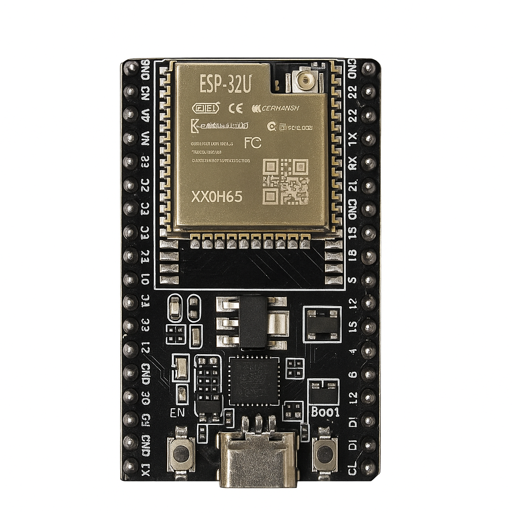 1×ESP32U DevKitC Type-C
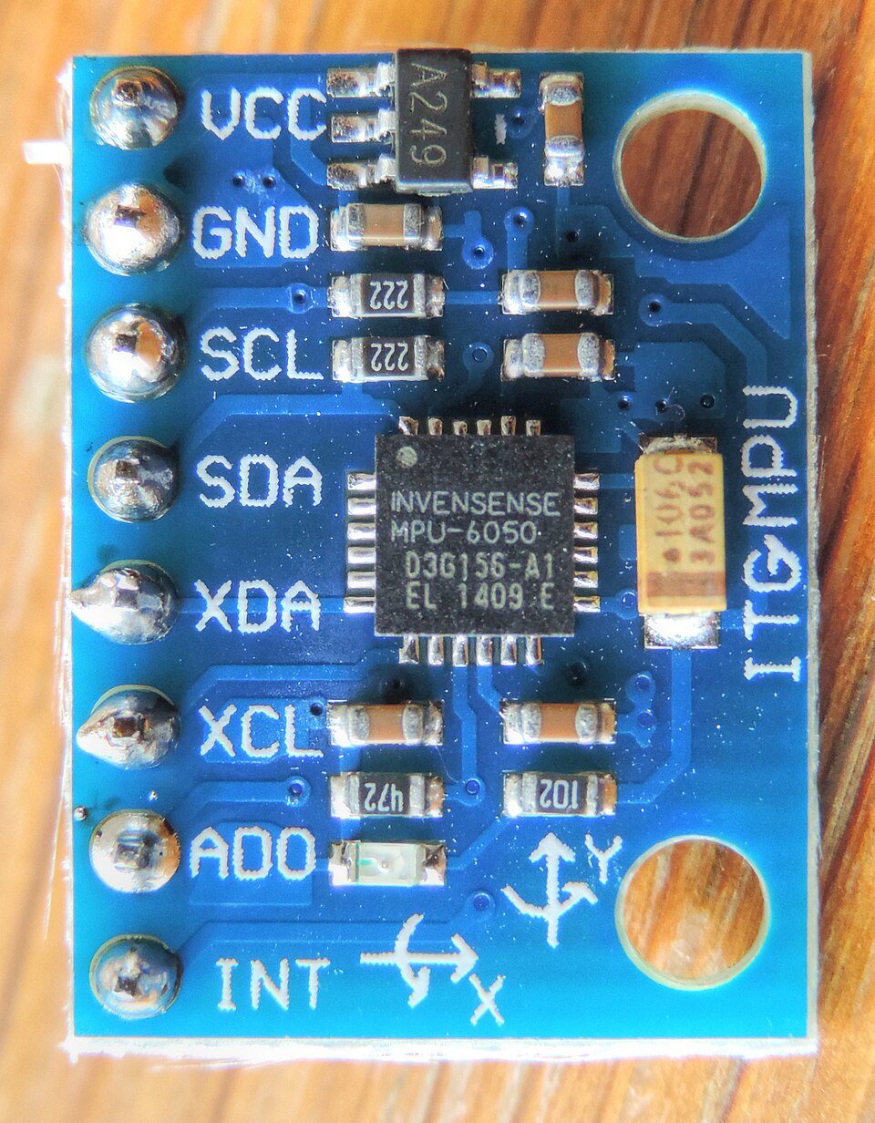 1×GY-521 MPU-6050 6DOF IMU Sensor Module
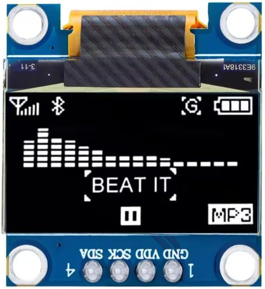 1×0.96" OLED Display Module 128x64 I2C (White)
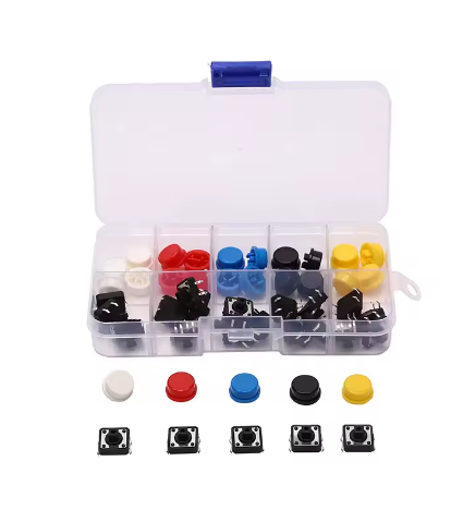 1×Tactile Microswitch Kit 25pcs 12x12x7.3mm Momentary Push Button Switches with Assorted Coloured Caps
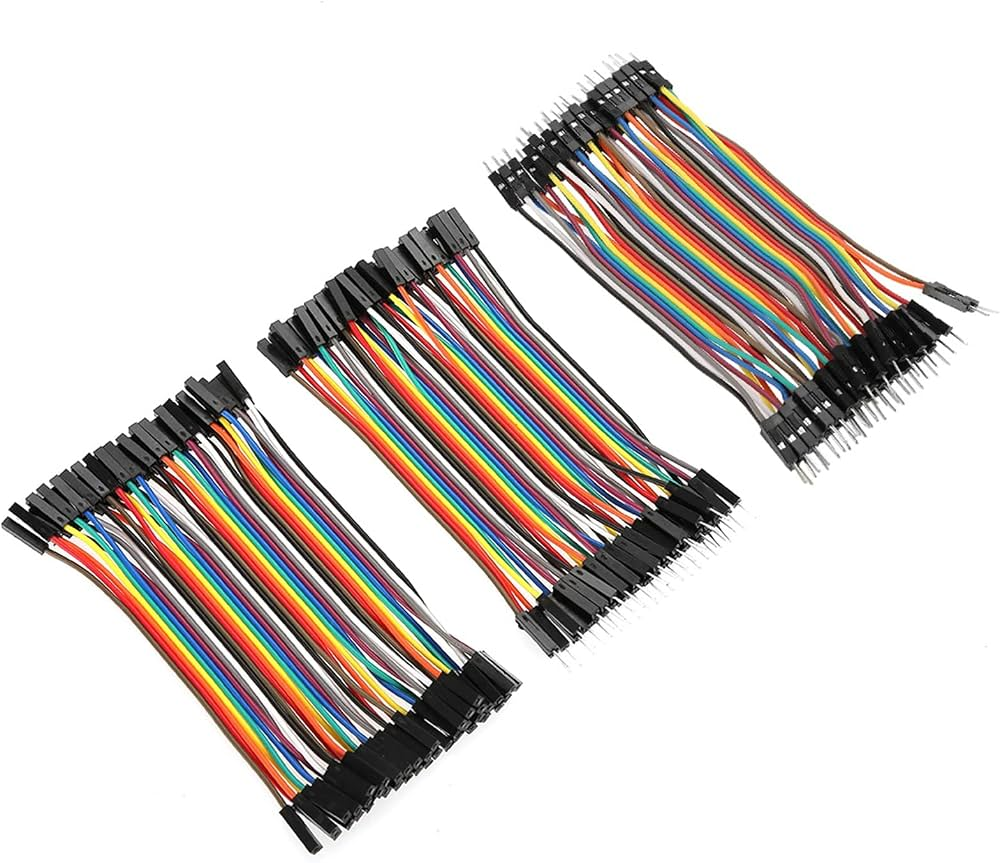 1×Jumper Wire Assorted Pack 120 Pieces
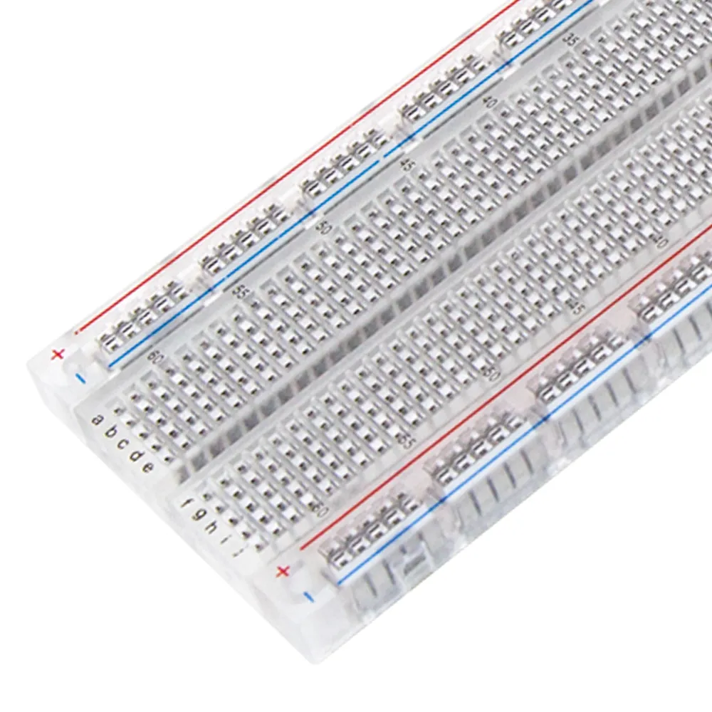 1×Transparent 830 Points Solderless Breadboard Clear Prototype Circuit Board MB-102 High Quality DIY Electronic Testing Experiment PCB Base with Power Plane
 1×Active Buzzer Module 5V DC (optional)
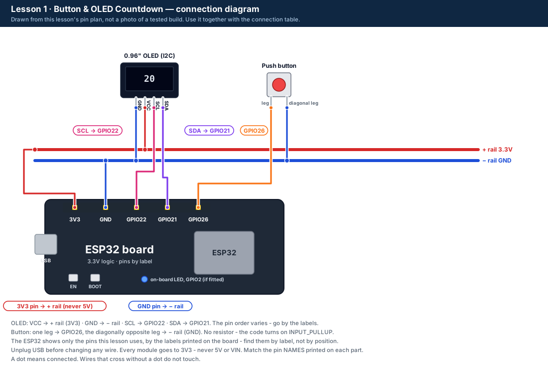 Connection diagram drawn from the pin plan - not a photo of a tested build. The table says the same in words.
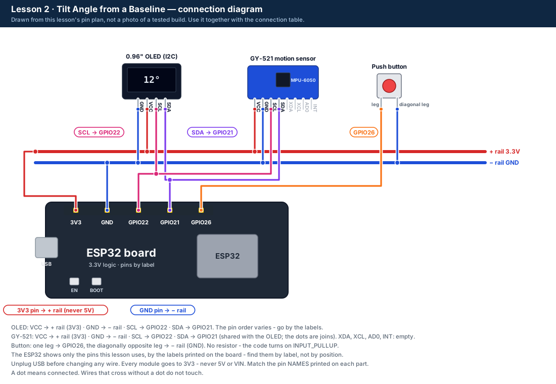 Connection diagram drawn from the pin plan - not a photo of a tested build. The table says the same in words.
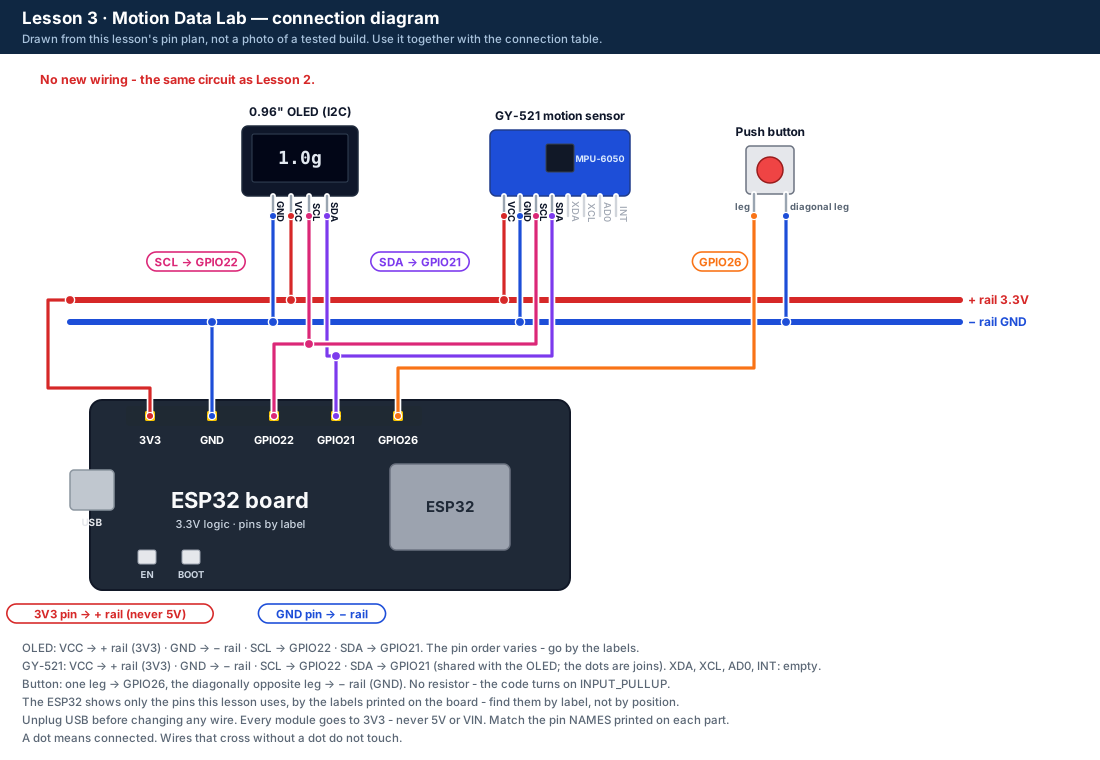 Connection diagram drawn from the pin plan - not a photo of a tested build. The table says the same in words.
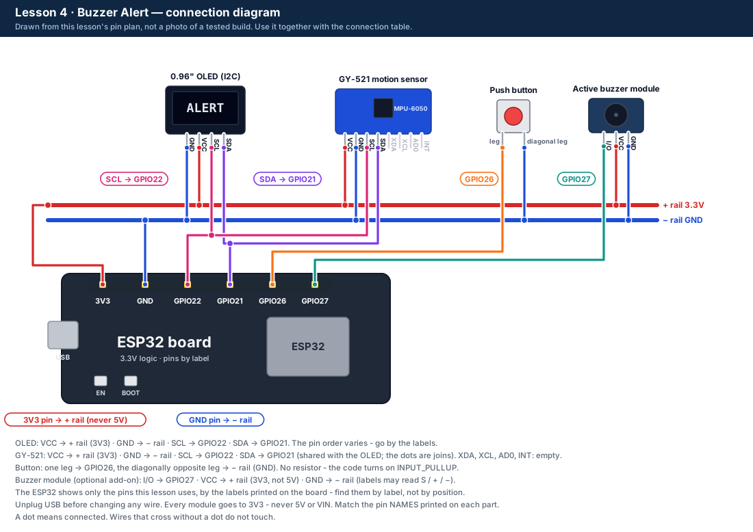 Connection diagram drawn from the pin plan - not a photo of a tested build. The table says the same in words.
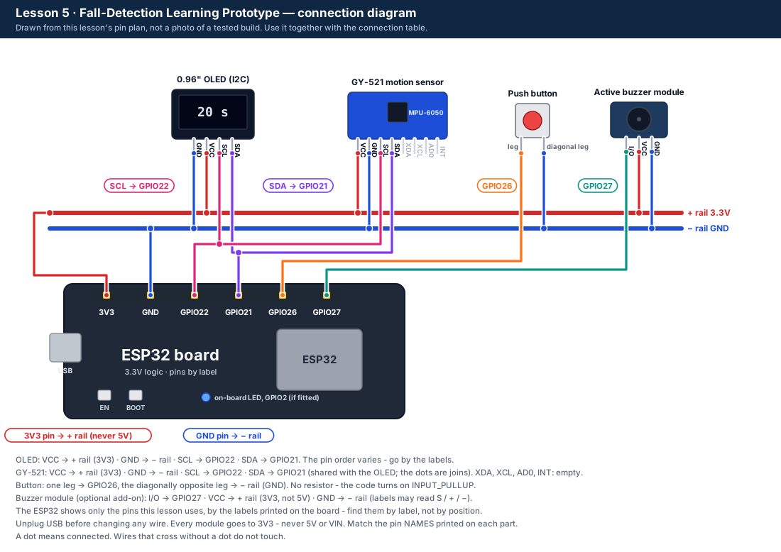 Connection diagram drawn from the pin plan - not a photo of a tested build. The table says the same in words.