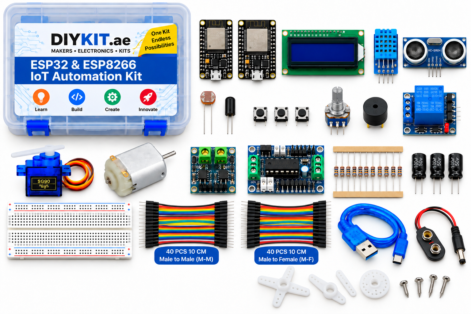
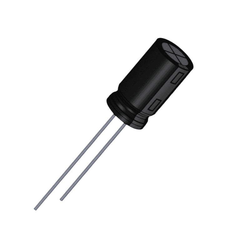
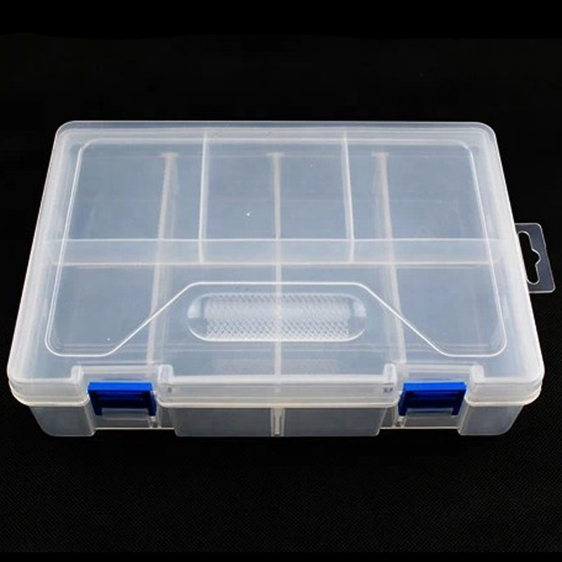
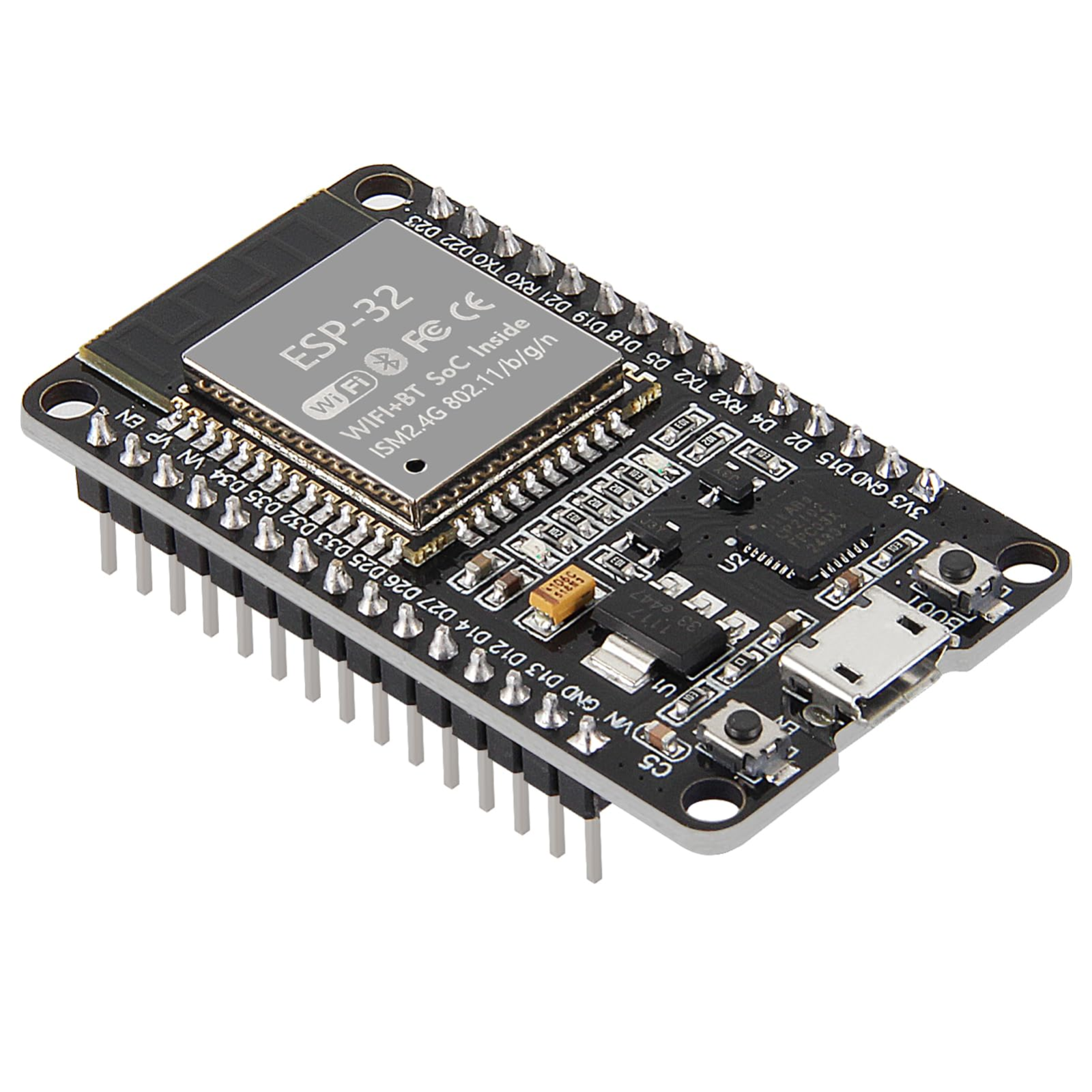
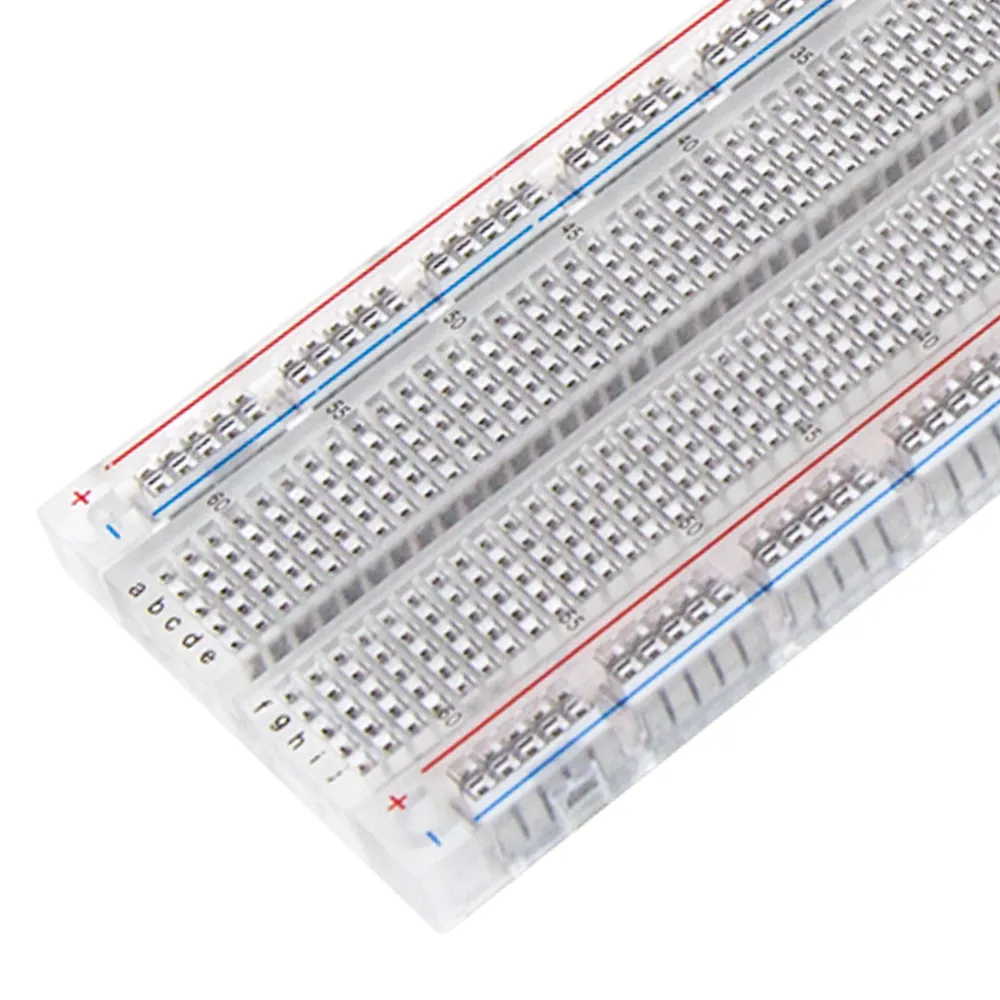
Two WiFi boards (ESP32 and ESP8266) with the sensors, drivers and output devices to build connected control projects: read temperature, humidity, light, tilt and distance, take analog input from a potentiometer, drive a servo and a DC motor through two different driver ICs, switch loads with a relay, sound a buzzer, and show results on a 16x2 LCD. Teaches the full progression - digital I/O, analog reading, PWM, I2C display, H-bridge motor control, switching real loads, WiFi and web servers, and finally two boards talking to each other across the network. Ships in a storage case with an 830-point breadboard, male-to-male and male-to-female jumper wires, an assorted resistor pack and capacitors, so nothing else is needed to start. Battery not included.
◈
Difficulty
Intermediate
◎
Build time
45-90 min
◇
Parts included
22 components
▦
Build guide
11 steps
// Components
Included parts (22)
22 parts packed in this kit
Component21 parts▾
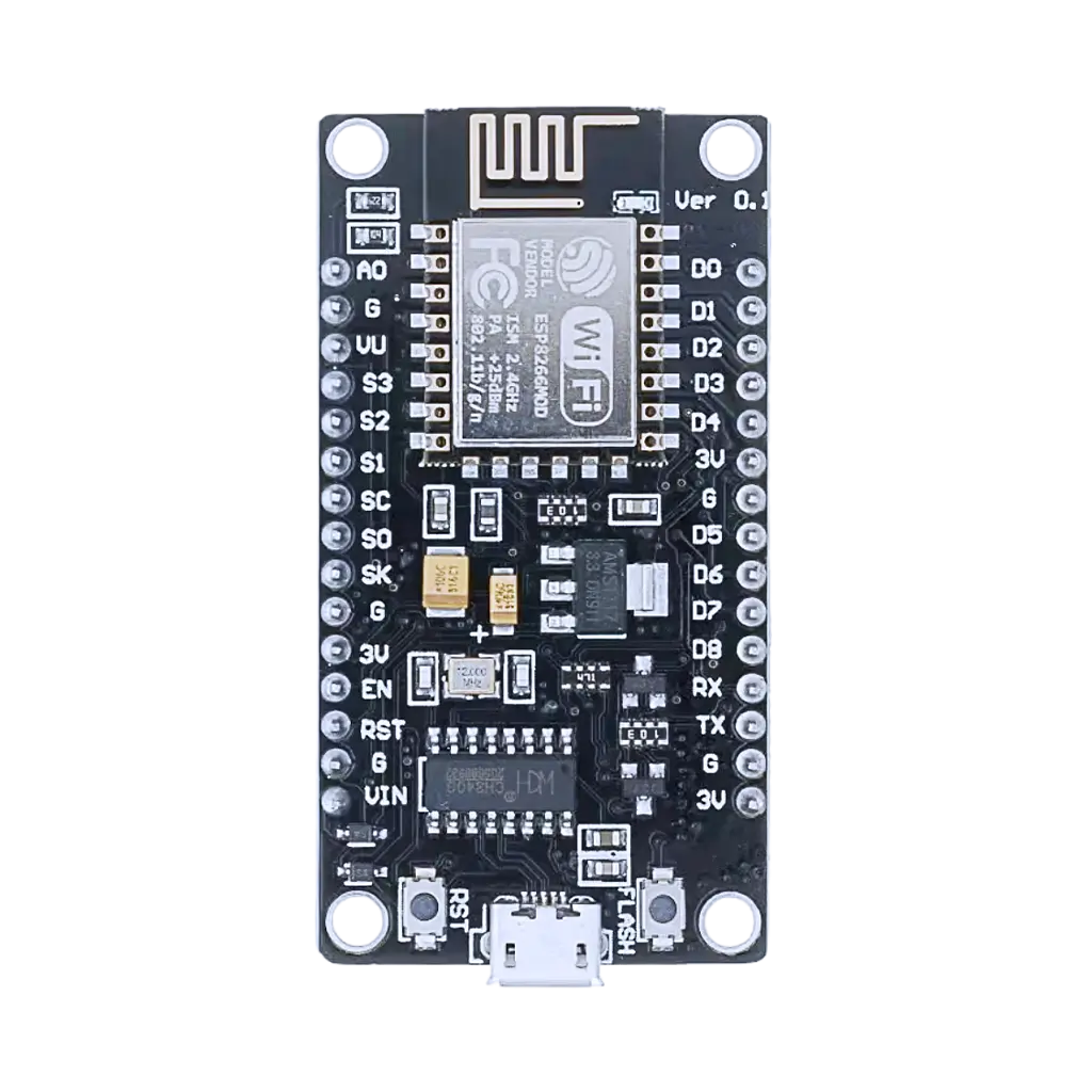
ESP8266 WiFi Serial Transceiver Module - Low-Power Wireless IoT Board for Arduino and Microcontroller ProjectsDIY-341
×1
Included
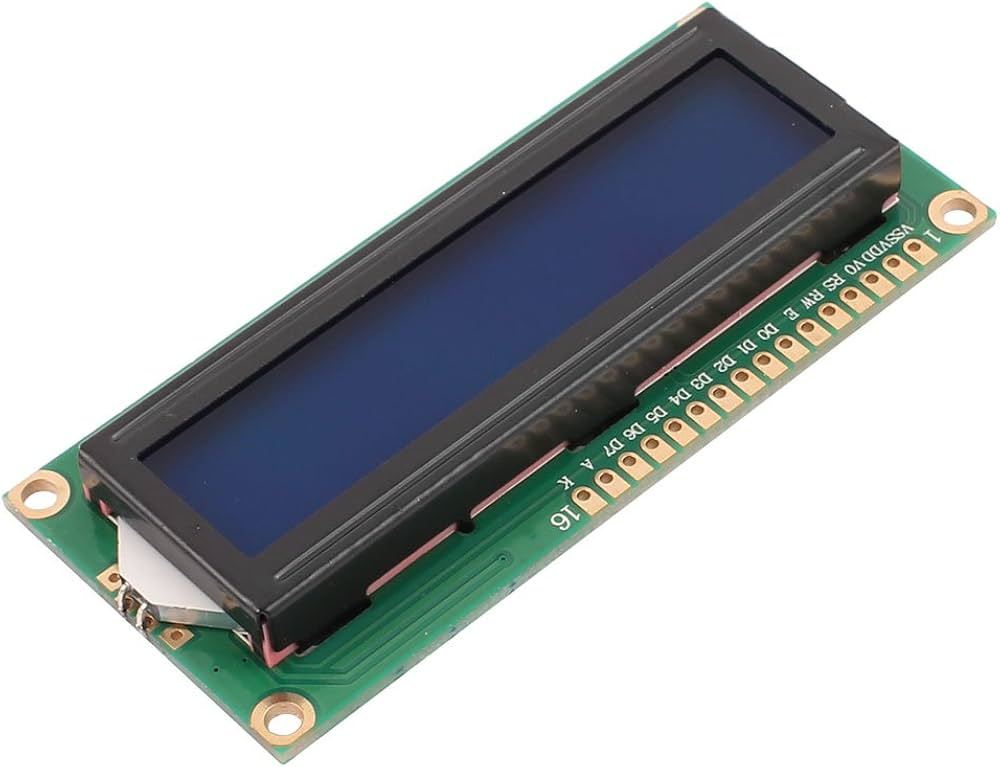
LCD 1602A Character Display Module - 16x2 HD44780 Controller, Blue Backlight, 5V for Arduino & Raspberry Pi D…DIY-211
×1
Included
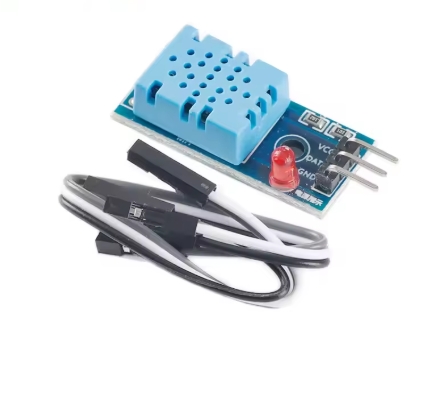
DHT11 Digital Temperature & Humidity Sensor Module, 3.3V–5V Single-Wire Output, Fast DIY Weather/Room Monitor…DHT11
Every one is built from parts in the box. Nothing extra to buy.
BasicsStarter01
Blink and read a button
Both boards carry an onboard LED, so your first sketch needs no wiring at all — blink it, change the timing, watch it obey. Then add a tactile switch to a GPIO pin with the internal pull-up enabled, and make the button control the LED. You will see one press register as three; that is contact bounce, and fixing it in software is the first real programming lesson in the kit. Ends with you understanding digital output, digital input and pull-ups, which every later project depends on.
ESP32NodeMCUtactile switchbreadboard
SensingStarter02
Read the room
The DHT11 sends both temperature and humidity down a single data wire using its own timing protocol, so a library does the decoding for you. Wire three pins, install the library, and print readings to the serial monitor. Watch the values settle over a minute — the sensor needs warm-up, and knowing that stops you chasing a fault that is not there. Half the projects below start from this one.
ESP32DHT11breadboard
AutomationStarter03
Light-triggered night light
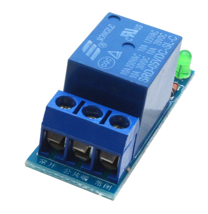
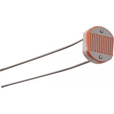
The photoresistor forms a voltage divider with a fixed resistor, and the board reads the midpoint on its analog pin. Below a threshold you pick, the relay closes and a lamp comes on. Note the relay module is low-level trigger, so the output pin must go LOW to switch it — a detail that catches people out. Add a delay before switching so a passing shadow does not flick the lamp on and off.
NodeMCUphotoresistorrelayresistors
DisplayStarter04
Analog control with a knob
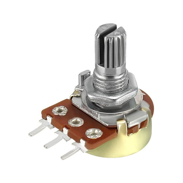
Read the potentiometer wiper on an analog pin and map the range to anything you need. Do it on both boards and the gap is obvious: the ESP32 offers several 12-bit ADC channels, the NodeMCU exactly one, A0, at 10 bits. You will also meet the NodeMCU's D0-D8 pin labels, which are not the GPIO numbers underneath. Between them, these two facts explain most sketches that work on one board and misbehave on the other.
ESP32potentiometerLCD1602
SensingIntermediate05
Temperature and humidity alarm
Show live readings on the LCD and sound the buzzer when the room crosses a threshold you set. The interesting part is what happens at the boundary: a naive version chatters on and off as the reading wobbles by a tenth of a degree. You fix it with hysteresis — switch on at one value, off at a lower one — which is the same technique a real thermostat uses.
ESP32DHT11buzzerLCD1602
SensingIntermediate06
Ultrasonic tape measure
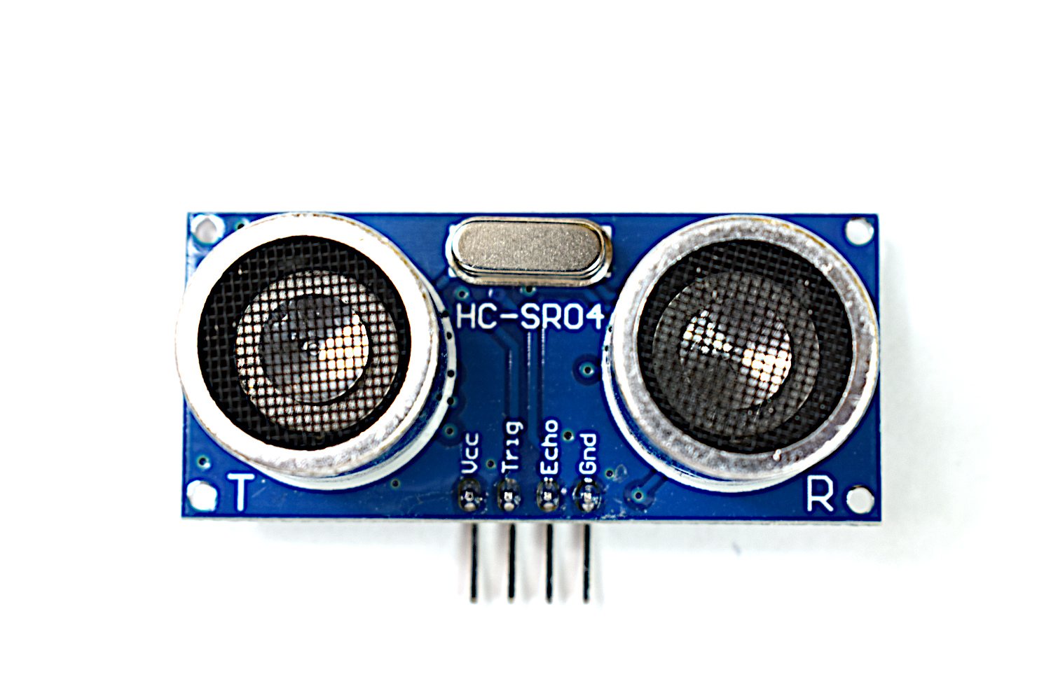
Send a pulse, time the echo, divide by two, convert to centimetres. Unlike an analog sensor this is a timing measurement, so you meet pulse timing and microsecond resolution. One safety point: the HC-SR04 is a 5V part and its echo pin outputs 5V, while both boards expect 3.3V — use a divider on that line rather than wiring it straight.
ESP32HC-SR04LCD1602
SensingIntermediate07
Parking assistant
Take the distance reading and turn it into beep rate: slow far away, faster as you close in, solid at the stop point. Short to build, and it teaches you to turn a number into something a person can act on without looking at a screen. Averaging a few readings stops a single bad echo from making it stutter.
ESP32HC-SR04buzzer
AutomationIntermediate08
Tank or bin level monitor
Mount the sensor above a container and measure the air gap to the surface — less gap means more contents. Invert the reading into a percentage, alert when it hits full or empty, and optionally drive a pump through the relay. The practical lesson is calibration: you measure the empty and full distances once and everything else is arithmetic.
NodeMCUHC-SR04buzzerrelay
MotionIntermediate09
Servo gate or pet feeder
The SG90 holds a commanded angle rather than just spinning, which is what makes it useful for gates, dispensers and valves. You drive it with a PWM pulse whose width sets the position. Power it from the 5V rail rather than a logic pin — the stall current on a small servo is more than a GPIO can give, and a browning-out board that resets mid-move is the classic first failure here.
ESP32SG90 servo
MotionIntermediate10
Motor speed control
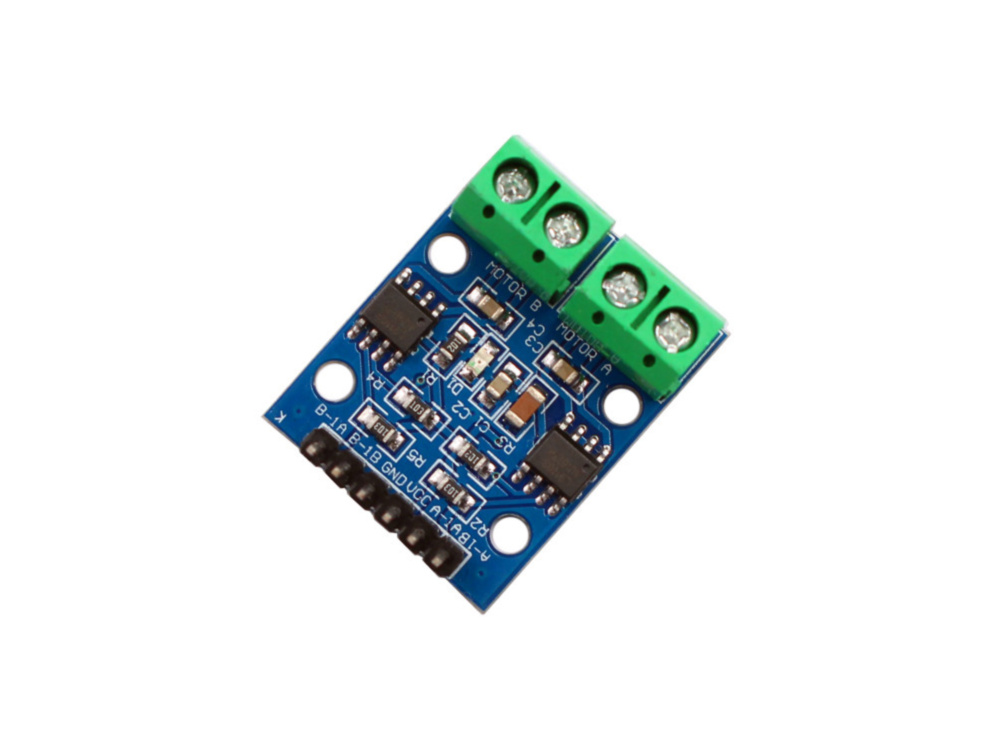
Turn the knob, the motor changes speed. PWM switches power on and off faster than the motor can respond, so average voltage falls and so does speed. You also learn why a motor never connects to a GPIO pin: it draws far too much current and dumps voltage spikes back down the line when it stops. The L9110 module handles both problems for you.
ESP32potentiometerDC motorL9110 module
MotionAdvanced11
Two drivers, one motor
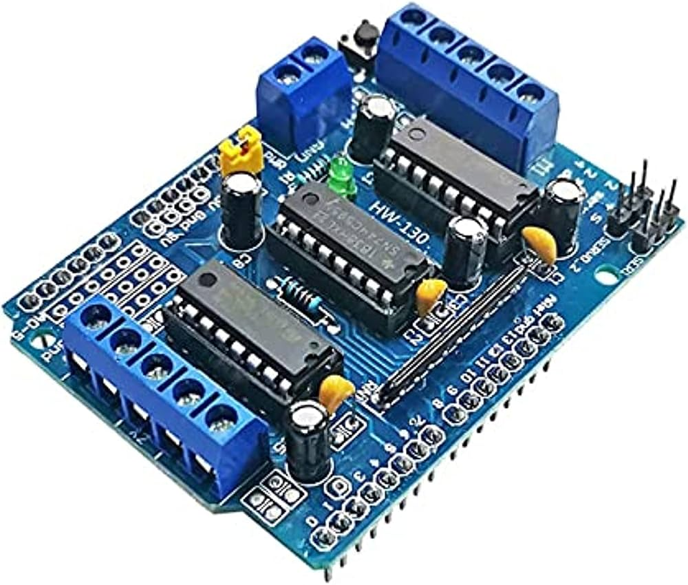
Run the same motor through both drivers and learn why there is more than one. The L9110 takes two pins per motor and you PWM one of them. The L293D separates the jobs: direction on the input pins, speed on a dedicated enable pin, which is the arrangement most driver chips use and the one worth knowing. The L293D also accepts a much higher motor supply, so it is the one you reach for when the motor is bigger than this kit's. Both have flyback diodes built in — wire a motor straight to a GPIO pin without one and you damage the board.
ESP32DC motorL293D moduleL9110 module
MotionAdvanced12
Radar-style scanner
Mount the ultrasonic sensor on the servo, sweep it through its range, and record distance at each angle. You now have a set of angle-and-distance pairs — a crude map of what is in front of the sensor. It pulls together PWM, pulse timing and display output in one build, and is the first project where the output is data rather than a single number.
ESP32SG90 servoHC-SR04LCD1602
SensingStarter13
Tilt and vibration alert
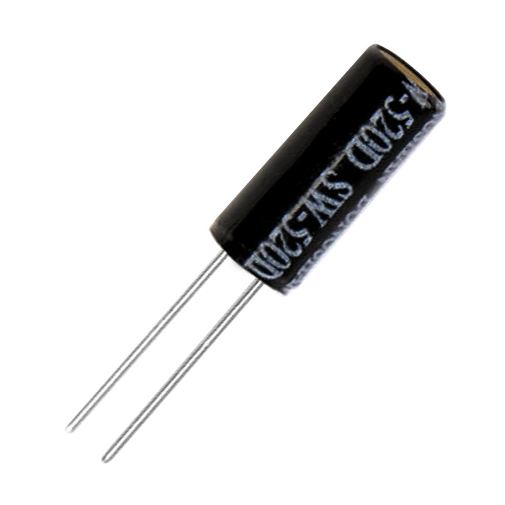
The SW-520D is a ball in a sealed tube: stand it upright and the leads connect, tilt it and they part. It is a bare two-lead component with no onboard circuitry, so you supply the pull-up yourself and read it exactly like a button — that is the lesson. Watch for the change rather than the level, debounce it, and latch the alert on until acknowledged instead of beeping once. Note it looks almost identical to a 100uF capacitor; check for the SW-520D marking before wiring.
NodeMCUSW-520D tilt switchbuzzer
NetworkIntermediate14
WiFi-controlled switch
Join your network, run a small web server on the board, and serve a page with a button that toggles the relay. The board's own IP becomes the address you open from a phone on the same network. This is the project most people buy an ESP32 for, and it is the first time the thing you built is reachable from somewhere else in the house.
ESP32relaybreadboard
NetworkAdvanced15
Live web dashboard
Serve a page showing temperature, humidity and light level, refreshing on its own so you never reload it. You will meet the reason embedded web work is fiddly: the board has little memory, so you build the page as a small template and send only the numbers on refresh rather than the whole document. Leave it running and the kit stops being a desk toy.
ESP32DHT11photoresistor
NetworkAdvanced16
Two-board sensor network
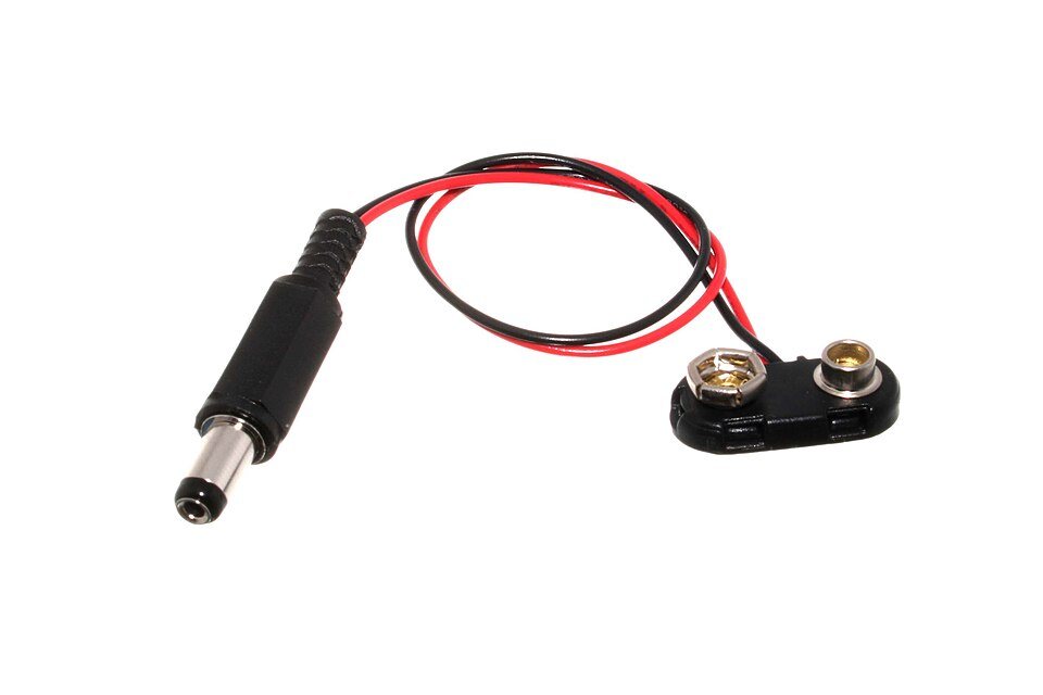
The NodeMCU sits with the sensor and posts its readings over WiFi; the ESP32 receives them and puts them on the LCD. Both boards run at once, so power one from USB and the other from the 9V battery snap, or use two cables. Two devices, one job, and everything that comes with that — what happens when a message is missed, how often to send, what the display should show when the sender goes quiet. This is the first distributed system most people build, and it is the reason the kit ships two boards instead of one.
NodeMCUESP32DHT11LCD1602
No projects in that group.
// Assembly
Build steps (11)
Tick steps off as you go — your place is kept on this device.
0 / 11
ℹ
These steps come from the build reference recorded for this kit. The firmware is in the Code section below.
// Firmware
Code
An example sketch, shown so the layout can be reviewed — it is not this kit's firmware.
Ask and we'll send the code written for your board.
Files1
Lines55
LanguageArduino C++
fall_alert_example.inoExample
#include <Wire.h>
#include <Adafruit_MPU6050.h>
#include <Adafruit_SSD1306.h>

// ── CONFIGURE THESE ──────────────────────────────
const char* WIFI_SSID = "YourNetworkName";
const char* WIFI_PASS = "YourPassword";
const float FALL_THRESHOLD = 2.5;    // g-force
const long  SNOOZE_MS      = 20000;  // 20 s
// ─────────────────────────────────────────────────

Adafruit_MPU6050 mpu;
Adafruit_SSD1306 display(128, 64, &Wire, -1);

#define BUZZER_PIN 25
#define BUTTON_PIN 26

void setup() {
  Serial.begin(115200);
  pinMode(BUZZER_PIN, OUTPUT);
  pinMode(BUTTON_PIN, INPUT_PULLUP);

  Wire.begin(21, 22);               // SDA, SCL — shared I2C bus
  if (!mpu.begin()) {
    Serial.println("MPU-6050 not found — check SDA/SCL wiring");
    while (1) delay(10);
  }
  display.begin(SSD1306_SWITCHCAPVCC, 0x3C);
  display.clearDisplay();
  display.display();
}

void loop() {
  sensors_event_t a, g, temp;
  mpu.getEvent(&a, &g, &temp);

  float magnitude = sqrt(a.acceleration.x * a.acceleration.x +
                         a.acceleration.y * a.acceleration.y +
                         a.acceleration.z * a.acceleration.z) / 9.81;

  if (magnitude > FALL_THRESHOLD) {
    digitalWrite(BUZZER_PIN, HIGH);
    unsigned long started = millis();
    while (millis() - started < SNOOZE_MS) {
      if (digitalRead(BUTTON_PIN) == LOW) {   // snoozed
        digitalWrite(BUZZER_PIN, LOW);
        return;
      }
      delay(20);
    }
    digitalWrite(BUZZER_PIN, LOW);
    sendAlert();                              // Wi-Fi notification
  }
  delay(20);                                  // ~50 samples / second
}
ℹ
This is a sample, not the firmware for this kit — the pin numbers match the example wiring above.
// Before you start
What this kit teaches
Two WiFi boards (ESP32 and ESP8266) with the sensors, drivers and output devices to build connected control projects: read temperature, humidity, light, tilt and distance, take analog input from a potentiometer, drive a servo and a DC motor through two different driver ICs, switch loads with a relay, sound a buzzer, and show results on a 16x2 LCD. Teaches the full progression - digital I/O, analog reading, PWM, I2C display, H-bridge motor control, switching real loads, WiFi and web servers, and finally two boards talking to each other across the network. Ships in a storage case with breadboard, male-to-male and male-to-female jumper wires, an assorted resistor pack and capacitors, so nothing else is needed to start. 15+ documented projects.
Difficulty · Intermediate
Assumes you have wired a breadboard before and are comfortable installing a toolchain. Nothing here needs soldering unless you choose to.
You'll also need
A computer for uploading code
A stable surface for breadboarding
Arduino IDE (free) installed
A multimeter — optional, but useful for checking connections
Who it's for
Catalogued as suited to iot / builders.
Classroom sets are quoted per seat — ask for a bulk price.
// Questions
Frequently asked
This kit is rated Intermediate. You should be comfortable with breadboard wiring before starting. It is built around the esp32 platform.
45-90 min. The build guide below breaks it into 11 steps.
All 22 components listed in the parts table, counted and checked before dispatch. 22 of them are in stock right now.
Recorded in our catalogue as suited to iot / builders. Bulk pricing is available for classroom sets.
AED 150.00 5 built and ready to ship
10%// first order
// Welcome
10% off your first order
Join the build list — new boards, restocks and the occasional teardown.
We'll send your discount code straight away.
// You're on the list
Here's your code
Apply it in the cart before checkout. It also lands in your inbox.