MAX30102 Heart Rate & SpO2 Pulse Oximeter Sensor Module with I2C Interface, INT Pin, 3.3V Logic, Arduino STM32 ESP32 Compatible for Wearable Health Monitoring Projects
Overview This MAX30102 Heart Rate and Blood Oxygen Sensor Module is a compact optical biosensing breakout designed for pulse detection (heart rate) and SpO2 estimation using photoplethysmography (PPG).
1x MAX30102 Heart Rate & SpO2 Sensor Module
Overview
This MAX30102 Heart Rate and Blood Oxygen Sensor Module is a compact optical biosensing breakout designed for pulse detection (heart rate) and SpO2 estimation using photoplethysmography (PPG). The MAX30102 integrates red and infrared LEDs, a photodetector, low-noise analog front end, and a digital signal chain that outputs sampled data over I2C. It is widely used in DIY wearable prototypes, health-monitoring demos, and embedded research projects where you want repeatable optical pulse waveforms without building a discrete analog front end.
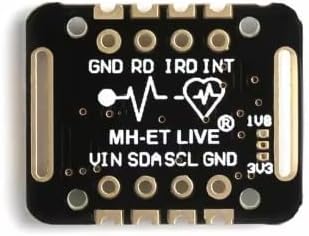
The pictured board provides clearly marked connections including VIN, SDA, SCL, GND plus additional pads such as INT and LED-related labels (RD/IRD). Exact pin behavior and onboard circuitry can vary by module revision, so always confirm the silkscreen and the seller’s wiring diagram against the MAX30102 datasheet and your specific breakout.
Technical Details
The MAX30102 works by driving the red and IR LEDs into tissue (typically a fingertip) and measuring the reflected light with the integrated photodiode. Blood volume changes with each heartbeat modulate the received light intensity, producing a PPG waveform. By alternating red and IR measurements and comparing absorption characteristics, algorithms can estimate SpO2. The sensor includes an internal FIFO and interrupt capability so your microcontroller can sleep between reads and wake only when new samples are ready, improving power efficiency in battery-powered designs.
Communication is performed via I2C (SDA/SCL). Data is read from sensor registers and FIFO, and configuration includes LED current, sample rate, pulse width, and ADC range (exact available settings depend on the MAX30102 and your library implementation; check datasheet). For best results, mechanical placement matters: stable contact pressure, reduced ambient light leakage, and minimal motion are critical. SpO2 is algorithm-dependent; the module provides raw red/IR readings and timing, while the accuracy of final SpO2 depends on calibration and signal processing.
Specifications
- Sensor IC: MAX30102 (integrated red + IR LEDs and photodetector)
- Measurement type: Reflective PPG for heart rate; red/IR ratio for SpO2 estimation (algorithm required)
- Interface: I2C (address and register map per MAX30102 datasheet; address may be fixed on the IC)
- Interrupt: INT pin available on breakout (active level and behavior per configuration; check datasheet)
- Supply / logic levels: Typically 3.3V logic; VIN/3V3 options vary by module revision (verify whether VIN includes regulation/level shifting before using 5V)
- Pins/labels (as shown on module): VIN, SDA, SCL, GND, INT, RD, IRD, 3V3 (exact function of RD/IRD depends on board design; commonly related to LED channels)
- Form factor: Small breakout PCB; exact dimensions and mounting hole pattern vary by module revision
Applications
- DIY pulse oximeter and heart rate monitor prototypes
- Wearable and fitness electronics proof-of-concepts
- Embedded signal processing projects (PPG filtering, peak detection, HRV experiments)
- IoT health telemetry demos (ESP32/STM32 + wireless logging)
- Educational labs for optical sensing and biomedical instrumentation basics
Integration Notes
Use short, clean I2C wiring and a solid ground reference to reduce noise. If your microcontroller is 5V (e.g., some Arduino boards), confirm whether the module supports 5V on VIN and whether SDA/SCL are level-shifted; if not, use a proper I2C level shifter and power the sensor at 3.3V. For stable readings, shield the sensor from ambient light and ensure consistent finger placement. Use a known-good MAX30102 library for your platform and tune LED current and sample rate to balance signal quality and power consumption. SpO2 results require calibration and are not a substitute for medical devices.
Included Components
1x MAX30102 Heart Rate & SpO2 Sensor Module
No reviews for this component yet.
Related Components