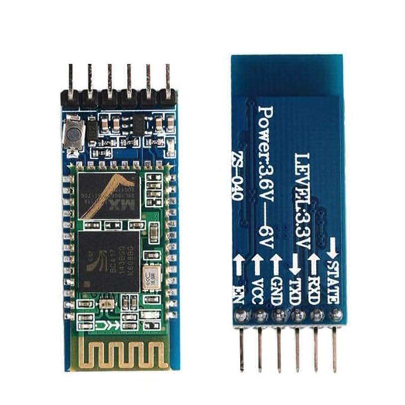
HC-05 Bluetooth Serial TTL UART Module with Backplane, Master/Slave Wireless Transceiver, 6-Pin Adapter Board, 3.3V-6V Supply, Compatible with Arduino ESP32 AVR PIC ARM
Overview The HC-05 Bluetooth wireless serial module is a classic Bluetooth (BR/EDR) transceiver designed to replace a wired UART cable with a short-range wireless link.
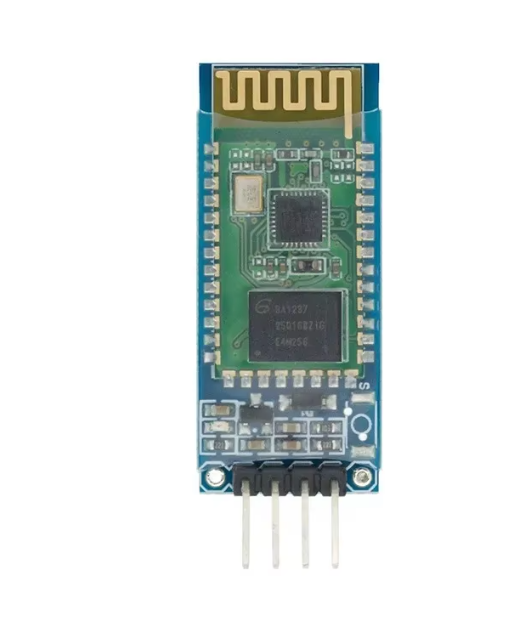
HC-05 Bluetooth module with 6-pin TTL UART backplane
Overview
The HC-05 Bluetooth wireless serial module is a classic Bluetooth (BR/EDR) transceiver designed to replace a wired UART cable with a short-range wireless link. It is commonly used for Bluetooth SPP (Serial Port Profile) style communication, allowing microcontrollers and embedded systems to transmit and receive serial data as if connected by a direct TTL UART connection. This version includes a 6-pin TTL-to-UART adapter backplane, making it easier to power the module and connect RX/TX lines using standard headers, breadboards, or Dupont jumpers.
Technical Details
HC-05 modules are widely used in prototyping and production-like DIY builds because they provide a simple UART interface while handling Bluetooth pairing and link management internally. Depending on the module revision and firmware, the HC-05 can typically operate in Slave mode (accepting connections from a phone/PC) and may also support Master mode (initiating a connection to another Bluetooth device). Configuration is generally performed through AT commands over the serial interface. How you enter AT mode (button/KEY pin behavior, power-up sequence, and baud rate used for AT commands) can vary by module revision, so it is important to confirm the correct procedure for your specific board.
The included backplane/adapter board is intended to simplify integration by providing a stable power input range and a convenient 6-pin header breakout. Many adapter boards include onboard regulation and level-conditioning features, but the exact electrical behavior (including whether RX is 3.3V tolerant only, whether a divider is present, and the regulator type) varies by manufacturer. For best reliability, treat the UART logic as 3.3V-level unless your specific module documentation confirms 5V-tolerant inputs. When interfacing with 5V microcontrollers, a simple resistor divider or level shifter on the module RX line is a common best practice if the board does not already include it.
Specifications
- Bluetooth type: Classic Bluetooth (BR/EDR); profile support commonly includes SPP (varies by firmware; check datasheet/AT list)
- Operating role: Master/Slave capable (availability and commands vary by module revision)
- Supply voltage (adapter/backplane input): 3.3V–6V (provided)
- UART logic level: typically 3.3V TTL (may vary by adapter design; verify before connecting 5V logic)
- Interface: TTL UART (TXD/RXD) plus control/status pins depending on the 6-pin mapping
- Pin count: 6-pin header on adapter board (exact pin names/order vary by board silkscreen; commonly VCC, GND, TXD, RXD, KEY/EN, STATE)
- Default baud rate: varies by firmware and configuration; check datasheet or query via AT commands
- Wireless range: varies by antenna design, environment, and power class; check module revision specifications
Applications
- Wireless serial bridge for Arduino and compatible boards (sensor telemetry, debug console, configuration link)
- Bluetooth-to-UART interface for embedded controllers (AVR, PIC, ARM) in robotics and automation
- PC/phone to microcontroller communication for DIY dashboards, data logging, and control panels
- Cable replacement for short-range serial devices and prototypes
- Pairing two microcontrollers using one module in Master mode and one in Slave mode (if supported by your firmware)
Integration Notes
1) Power: Supply the adapter board within 3.3V–6V as specified. If powering from a noisy source (motors/servos), add local decoupling near the module and keep power wiring short.
2) UART wiring: Cross-connect TX to RX and RX to TX, and share a common ground. Confirm the module’s UART voltage requirements; if your MCU uses 5V UART and the module RX is not 5V tolerant, use a level shifter or resistor divider.
3) AT configuration: Enter AT mode using the method required by your board revision (often involving a KEY/EN pin or a button during power-up). Use the correct AT baud rate for your firmware.
4) ESP32 note: ESP32 UART is 3.3V logic, which typically matches HC-05 UART levels well. Choose a free hardware UART or remap pins as needed.
5) Mounting and RF: Keep the antenna area clear of metal and high-current traces for better link stability. Orientation and enclosure materials can affect range.
Included Components
HC-05 Bluetooth module with 6-pin TTL UART backplane
No reviews for this component yet.
Related Components