 Backorder
IR Infrared Transmitter + Receiver Module Set 38KHz, Digital IR Sensor Pair with 3-Pin Interface for Arduino UNO Mega Nano, DIY Remote Control Decode/Send, Electronic Building Block
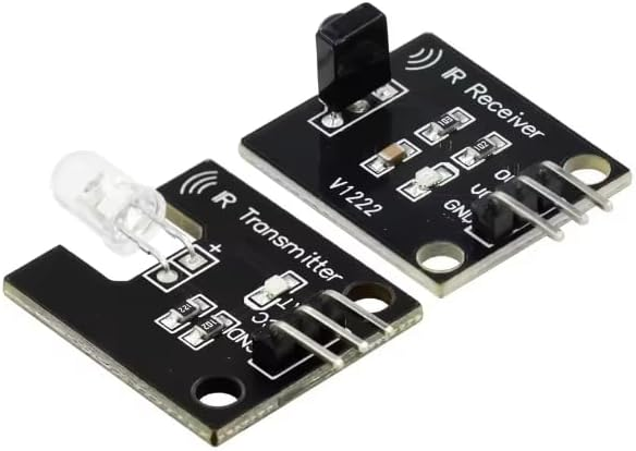
Overview This IR Infrared Transmitter and Receiver Module Set is designed for DIY electronics and microcontroller projects that need reliable infrared communication using a 38kHz carrier. The set includes one IR transmitter board (IR LED emitter) and one IR receiver board (demodulating IR sensor).
1x IR Transmitter Module, 1x IR Receiver Module
Overview
This IR Infrared Transmitter and Receiver Module Set is designed for DIY electronics and microcontroller projects that need reliable infrared communication using a 38kHz carrier. The set includes one IR transmitter board (IR LED emitter) and one IR receiver board (demodulating IR sensor). Together they enable common tasks such as receiving and decoding IR remote control signals, building custom IR remotes, creating short-range IR links, and adding simple line-of-sight signaling to robotics and automation projects.
Unlike raw photodiodes that require analog amplification and filtering, the receiver module in this set is built around a demodulating IR receiver device tuned for 38kHz. This type of receiver filters ambient light and rejects most non-modulated IR sources, outputting a digital pulse stream that corresponds to the incoming IR bursts. The transmitter module provides an IR LED on a small PCB so you can drive it with a microcontroller-generated carrier (typically PWM at ~38kHz) and encode data using burst patterns.
Technical Details
Receiver module behavior: The IR receiver board typically provides a digital output labeled DO. When a 38kHz-modulated IR signal is detected, the demodulator outputs a logic-level waveform representing the envelope of the bursts (polarity and idle state vary by receiver part and board revision—check your module markings and test with a scope or serial monitor). Because the receiver is tuned for a specific carrier frequency, best results are achieved when the transmitter is driven at 38kHz and the data is encoded as bursts (as used by common IR protocols).
Transmitter module behavior: The IR transmitter board uses an IR LED intended to be driven with a modulated signal rather than steady DC. For maximum range, the LED is commonly pulsed at 38kHz with short bursts at a duty cycle appropriate for the LED and driver. Some module revisions include a transistor driver stage and/or current-limiting components; others may rely on the controller pin and onboard resistor values. Because IR LED current capability and onboard resistor values can vary by module revision, verify the board’s resistor markings and ensure your drive method stays within safe current limits for both the LED and your MCU GPIO.
Power and logic interfacing: These modules are commonly used with 5V Arduino boards, but many demodulating receiver ICs also support lower voltages (exact range varies by receiver part—check datasheet). If using 3.3V MCUs (ESP32, Raspberry Pi Pico, etc.), confirm the receiver output logic level and power requirements for your specific board revision. Always connect GND between the module and controller for stable operation.
Noise and ambient light considerations: IR receivers are designed to reject steady IR from sunlight and lamps, but strong ambient IR can still reduce range. For best performance, use line-of-sight alignment, avoid direct sunlight on the receiver, and consider adding a simple shroud or tube around the receiver to narrow its field of view.
Specifications
- Set contents: 1x IR transmitter module, 1x IR receiver module
- Carrier frequency (receiver): 38kHz (tuned demodulation)
- Output type (receiver): Digital output (DO), logic-level pulses (polarity varies by module revision)
- Interface pins: 3-pin header on each module (typically VCC, GND, signal/DO; labeling may vary)
- Supply voltage: Varies by module revision and receiver IC; commonly used at 5V, confirm on PCB/datasheet
- IR wavelength: Typical IR LED wavelength varies by LED used (commonly around 940nm; check LED specification if critical)
- Range: Depends on LED drive current, optics, ambient light, and alignment; varies by build
- Mounting: PCB mounting holes (size/spacing varies by module revision)
Applications
- Arduino IR remote receiver projects (decode TV/AC remote codes)
- Custom IR transmitter/remote projects (send NEC/RC5-style codes with 38kHz carrier)
- Robot communication and simple line-of-sight signaling
- IR break-beam style experiments (with proper alignment and modulation)
- Educational electronics building blocks for digital sensing and communication labs
Integration Notes
- For receiving: Connect receiver VCC and GND, then connect DO to a digital input pin. Use an IR decoding library compatible with your platform (e.g., common Arduino IR receiver libraries) and verify the expected output polarity.
- For transmitting: Drive the transmitter signal pin with a 38kHz PWM/carrier and gate it in bursts to encode data. If your module lacks a transistor driver, avoid overcurrent from a GPIO pin; use an external transistor/MOSFET driver if higher LED current is needed.
- Always share ground between modules and the controller. If you experience unstable readings, add decoupling near VCC (value depends on your setup) and keep signal wires short.
Included Components
1x IR Transmitter Module, 1x IR Receiver Module
No reviews for this component yet.
Related Components