Analog control with a knob
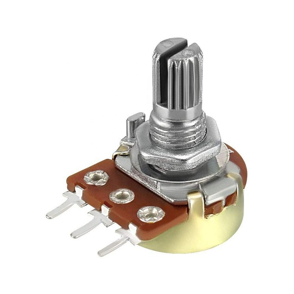
Read the potentiometer wiper on an analog pin and map the range to anything you need. Do it on both boards and the gap is obvious: the ESP32 offers several 12-bit ADC channels, the NodeMCU exactly one, A0, at 10 bits. You will also meet the NodeMCU's D0-D8 pin labels, which are not the GPIO numbers underneath. Between them, these two facts explain most sketches that work on one board and misbehave on the other.
What this project uses
Every item is in the kit — nothing extra to buy.
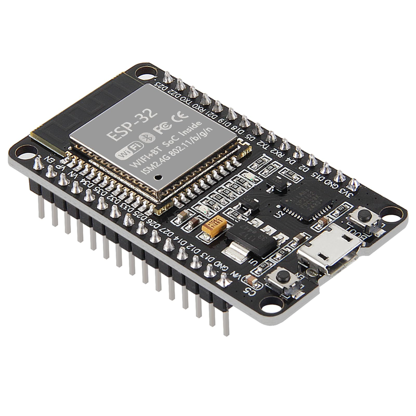
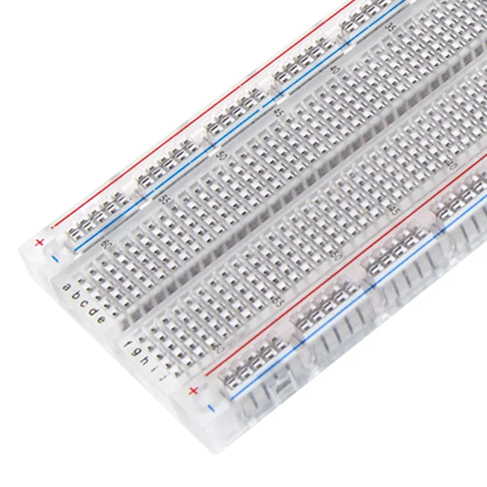


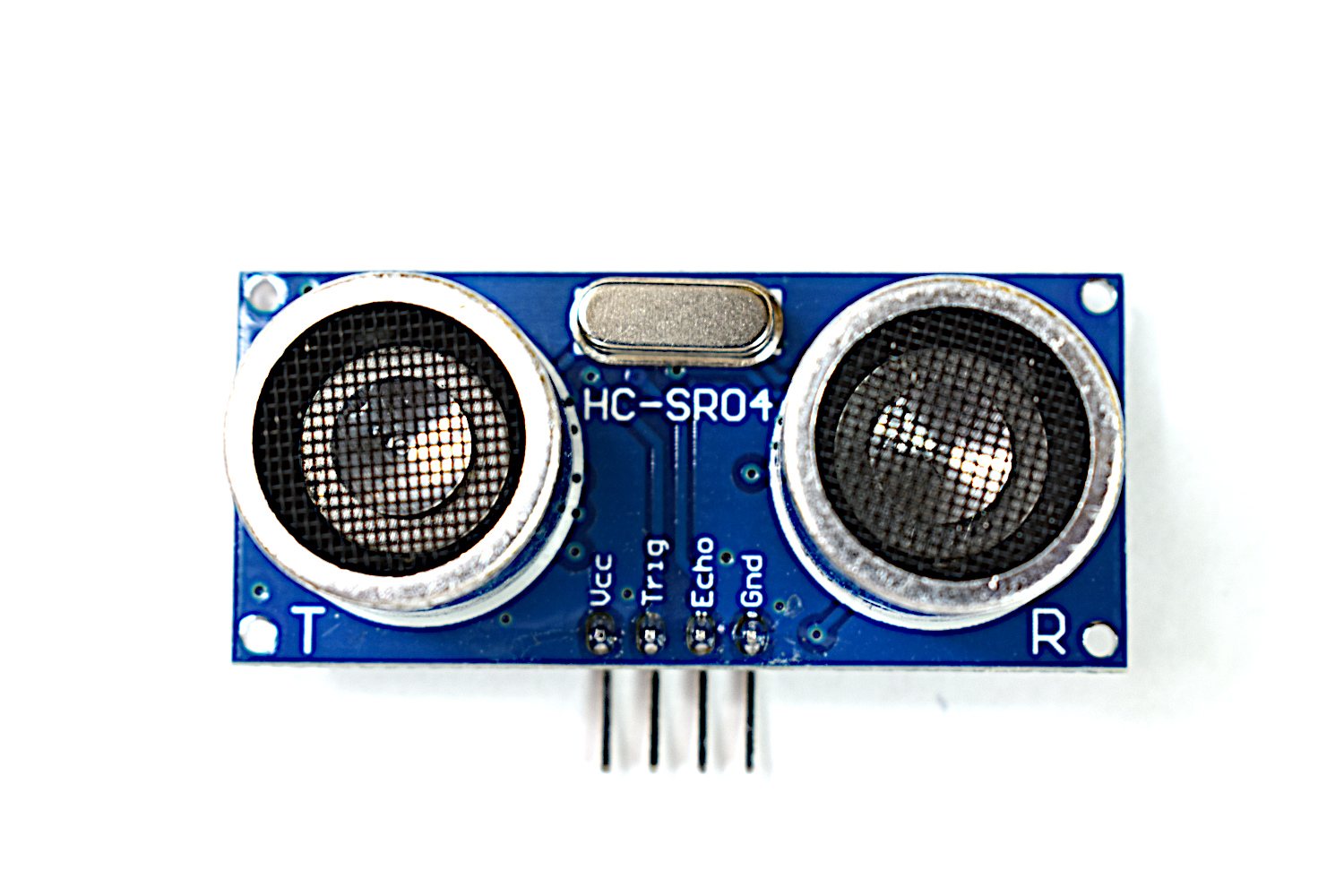

ESP32 & ESP8266 IoT Automation Kit
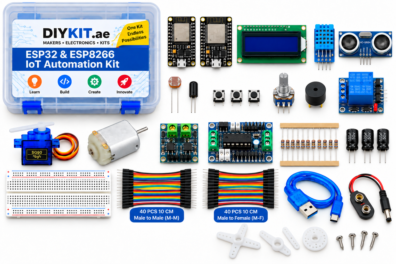
All 24 parts in one box, with this project and 15 more to build from them.
Need only these parts? Order them loose · from AED 110.74
One of each part. Packs (resistor assortment, jumper wires) already hold more than a single build needs. Backorder parts ship once they arrive — the kit above has every part boxed today. Delivery is free on orders AED 150.00+.
Sketch for this project
Written for the board in the kit. Copy it into the Arduino IDE; change the pin numbers if you wire it differently.
/*
  04 — Analog control with a knob
  Boards: ESP32 or NodeMCU V3 ESP8266 development board — same sketch, and the point is the difference.
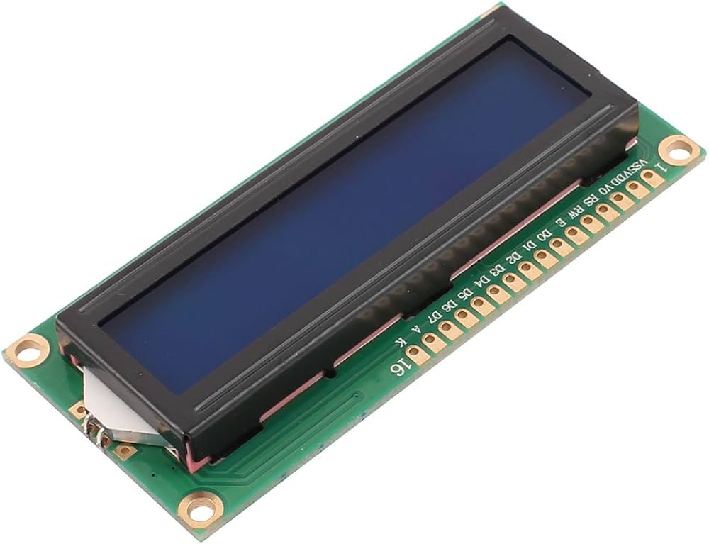
  Parts: potentiometer, LCD 1602 (I2C backpack).
  Library: "LiquidCrystal I2C" by Frank de Brabander.

  Wiring:
    Potentiometer: outer legs -> 3V3 and GND, middle (wiper) -> ESP32 GPIO 35 / NodeMCU A0
    LCD (I2C):     VCC -> VIN (5 V), GND -> GND, SDA -> ESP32 GPIO 21 / NodeMCU D2,
                   SCL -> ESP32 GPIO 22 / NodeMCU D1

  ESP32: several 12-bit ADC inputs (0..4095). NodeMCU: exactly one, A0, 10-bit
  (0..1023). And NodeMCU's D-labels are not GPIO numbers. Those two facts explain
  most sketches that work on one board and misbehave on the other.
*/

#include <Wire.h>
#include <LiquidCrystal_I2C.h>

#if defined(ESP32)
  const int POT_PIN = 35;       // ADC1 — keeps working when WiFi is on
  const int ADC_MAX = 4095;
#elif defined(ESP8266)
  const int POT_PIN = A0;
  const int ADC_MAX = 1023;
#else
  #error "Select an ESP32 or ESP8266 board"
#endif

LiquidCrystal_I2C lcd(0x27, 16, 2);   // if the LCD stays blank, try 0x3F

void setup() {
  Serial.begin(115200);
  lcd.init();
  lcd.backlight();
  lcd.print("Turn the knob");
}

void loop() {
  int raw = analogRead(POT_PIN);
  int percent = map(raw, 0, ADC_MAX, 0, 100);

  lcd.setCursor(0, 0);
  lcd.print("raw: "); lcd.print(raw); lcd.print("    ");
  lcd.setCursor(0, 1);
  lcd.print("level: "); lcd.print(percent); lcd.print("%   ");

  // Bar graph on the right of line 2: 0..5 blocks
  lcd.setCursor(11, 1);
  int blocks = map(raw, 0, ADC_MAX, 0, 5);
  for (int i = 0; i < 5; i++) lcd.print(i < blocks ? "\xFF" : " ");

  delay(100);
}More from this kit
Blink and read a button
Both boards carry an onboard LED, so your first sketch needs no wiring at all — blink it, change the timing, watch it obey. Then add a tactile switch to a GPIO pin with…
Read the room
The DHT11 sends both temperature and humidity down a single data wire using its own timing protocol, so a library does the decoding for you. Wire three pins, install the…
Light-triggered night light
The photoresistor forms a voltage divider with a fixed resistor, and the board reads the midpoint on its analog pin. Below a threshold you pick, the relay closes and a l…