Blink and read a button
Both boards carry an onboard LED, so your first sketch needs no wiring at all — blink it, change the timing, watch it obey. Then add a tactile switch to a GPIO pin with the internal pull-up enabled, and make the button control the LED. You will see one press register as three; that is contact bounce, and fixing it in software is the first real programming lesson in the kit. Ends with you understanding digital output, digital input and pull-ups, which every later project depends on.
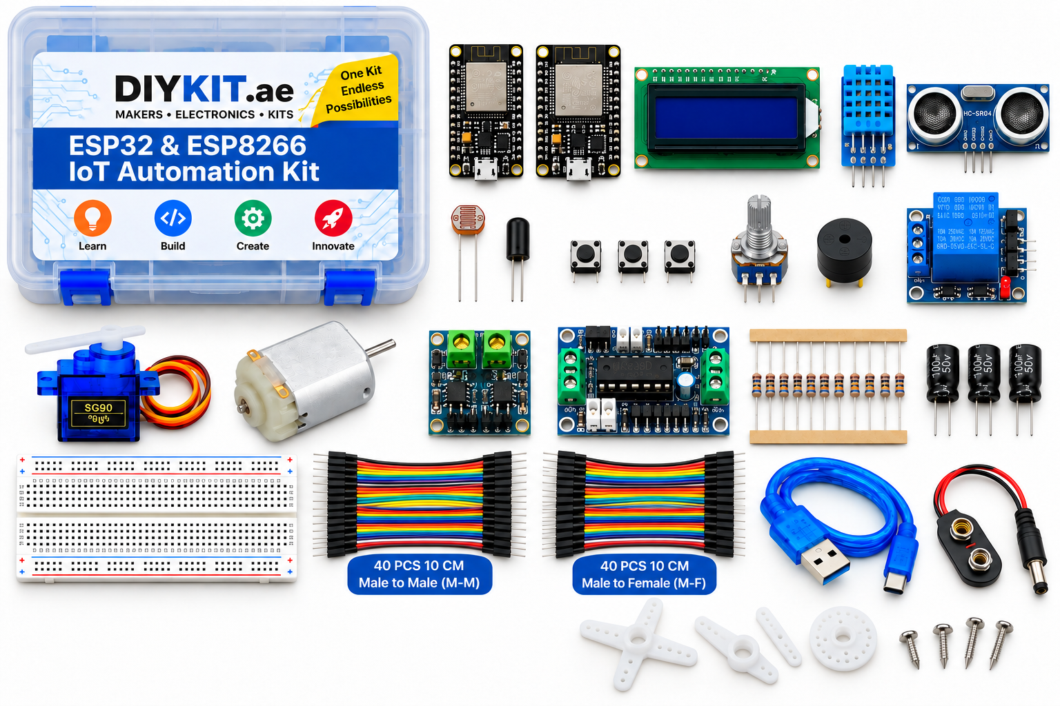
What this project uses
Every item is in the kit — nothing extra to buy.
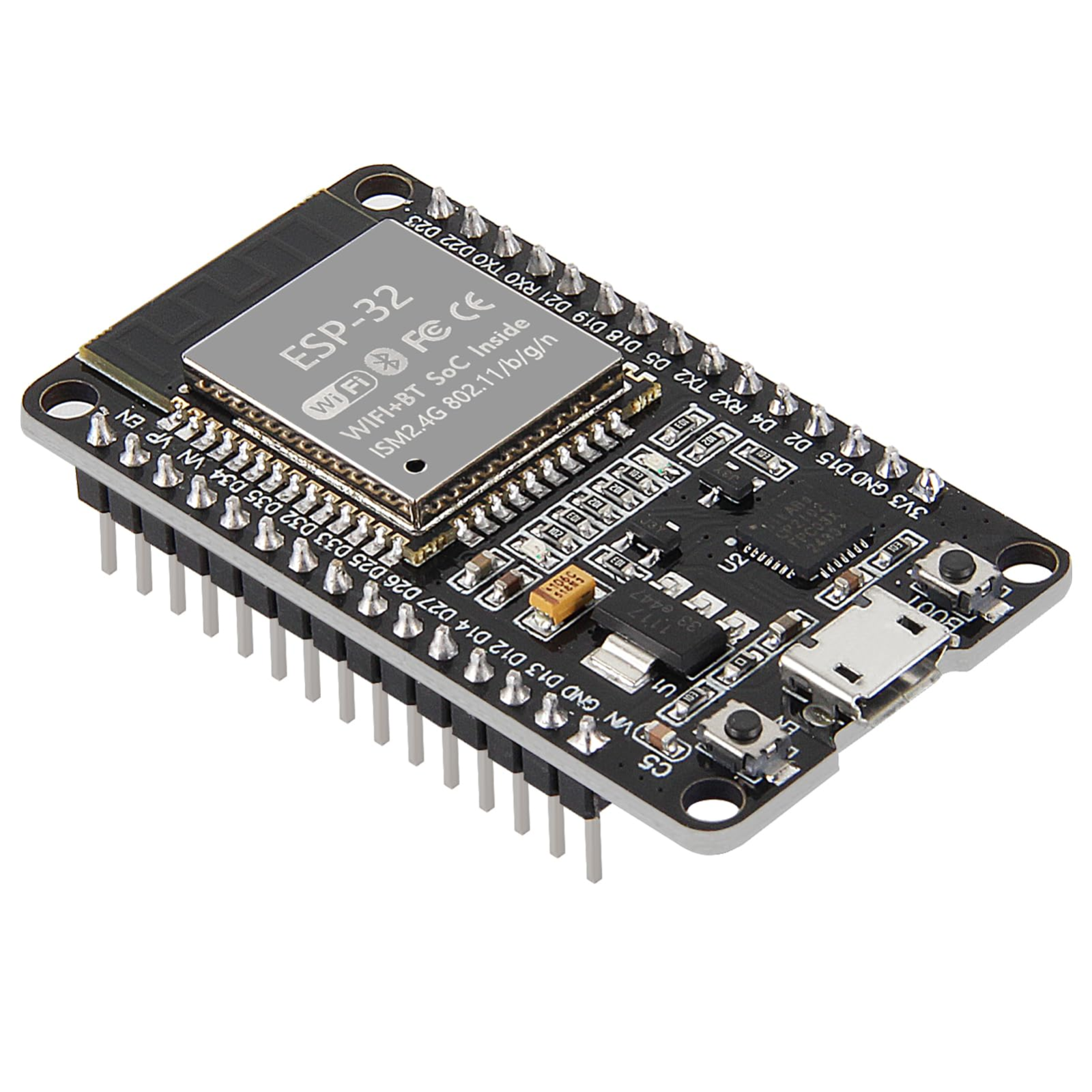
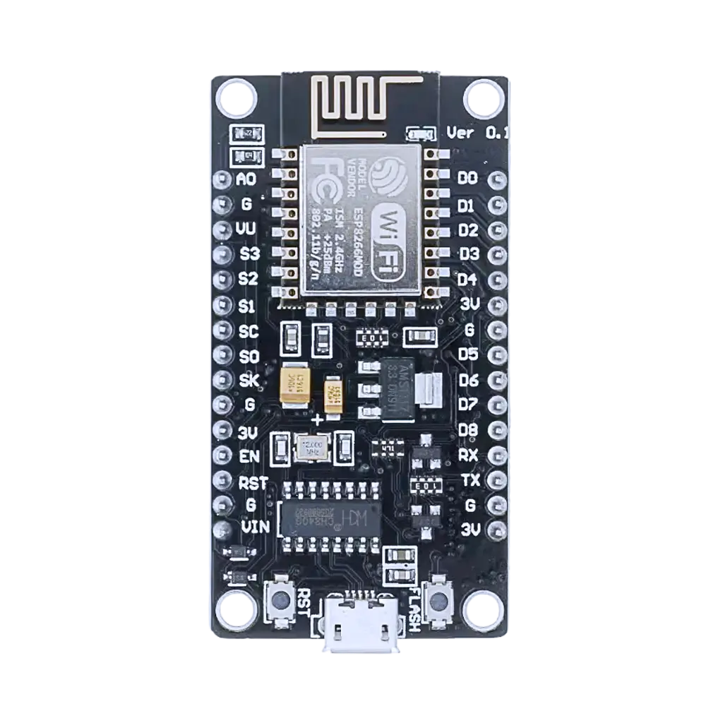
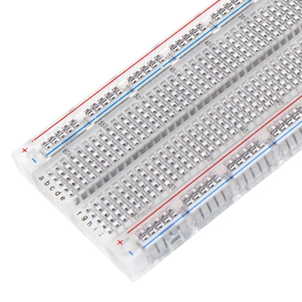



ESP32 & ESP8266 IoT Automation Kit
All 24 parts in one box, with this project and 15 more to build from them.
Need only these parts? Order them loose · from AED 122.47
One of each part. Packs (resistor assortment, jumper wires) already hold more than a single build needs. Backorder parts ship once they arrive — the kit above has every part boxed today. Delivery is free on orders AED 150.00+.
Sketch for this project
Written for the board in the kit. Copy it into the Arduino IDE; change the pin numbers if you wire it differently.
/*
  01 — Blink and read a button
  Kit: ESP32 & ESP8266 IoT Automation Kit (DIY KIT UAE)
  Boards: ESP32 or NodeMCU V3 ESP8266 development board — same sketch, pick the board in the IDE.
  Parts: onboard LED, tactile switch, breadboard, jumper wires. No library.
  Optional: a 5 mm LED from the kit in series with a 220 ohm resistor, long leg
  to the pin below and short leg to GND — then change LED_PIN to that pin
  (ESP32: GPIO 26; NodeMCU: D1) and LED_ON to HIGH.

  Wiring (button): one leg to the pin below, the other leg to GND.
  The internal pull-up holds the pin HIGH; pressing pulls it LOW.
    ESP32:   button -> GPIO 27      LED = onboard, GPIO 2 (HIGH = on)
    NodeMCU: button -> D5           LED = onboard, D4  (LOW  = on)

  What you learn: digital output, digital input with a pull-up, and why one
  press can register as three (contact bounce) — fixed with a 30 ms debounce.
*/

#if defined(ESP32)
  const int BUTTON_PIN = 27;
  const int LED_PIN    = 2;
  const bool LED_ON    = HIGH;
#elif defined(ESP8266)
  const int BUTTON_PIN = D5;
  const int LED_PIN    = LED_BUILTIN;   // D4 on NodeMCU
  const bool LED_ON    = LOW;           // wired between 3V3 and the pin, so LOW lights it
#else
  #error "Select an ESP32 or ESP8266 board"
#endif

bool ledState = false;
int  lastReading = HIGH;
int  stableState = HIGH;
unsigned long lastChange = 0;
const unsigned long DEBOUNCE_MS = 30;

void setup() {
  Serial.begin(115200);
  pinMode(LED_PIN, OUTPUT);
  pinMode(BUTTON_PIN, INPUT_PULLUP);

  // Part 1: no wiring at all — blink the onboard LED three times.
  for (int i = 0; i < 3; i++) {
    digitalWrite(LED_PIN, LED_ON);  delay(200);
    digitalWrite(LED_PIN, !LED_ON); delay(200);
  }
  Serial.println("Press the button to toggle the LED.");
}

void loop() {
  // Part 2: the button toggles the LED — one toggle per press, debounced.
  int reading = digitalRead(BUTTON_PIN);
  if (reading != lastReading) {
    lastChange = millis();          // contact is bouncing: restart the timer
    lastReading = reading;
  }
  if (millis() - lastChange > DEBOUNCE_MS && reading != stableState) {
    stableState = reading;          // it has been steady long enough to trust
    if (stableState == LOW) {       // LOW = pressed (pull-up)
      ledState = !ledState;
      digitalWrite(LED_PIN, ledState ? LED_ON : !LED_ON);
      Serial.println(ledState ? "LED on" : "LED off");
    }
  }
}More from this kit
Read the room
The DHT11 sends both temperature and humidity down a single data wire using its own timing protocol, so a library does the decoding for you. Wire three pins, install the…
Light-triggered night light
The photoresistor forms a voltage divider with a fixed resistor, and the board reads the midpoint on its analog pin. Below a threshold you pick, the relay closes and a l…
Analog control with a knob
Read the potentiometer wiper on an analog pin and map the range to anything you need. Do it on both boards and the gap is obvious: the ESP32 offers several 12-bit ADC ch…