Tank or bin level monitor
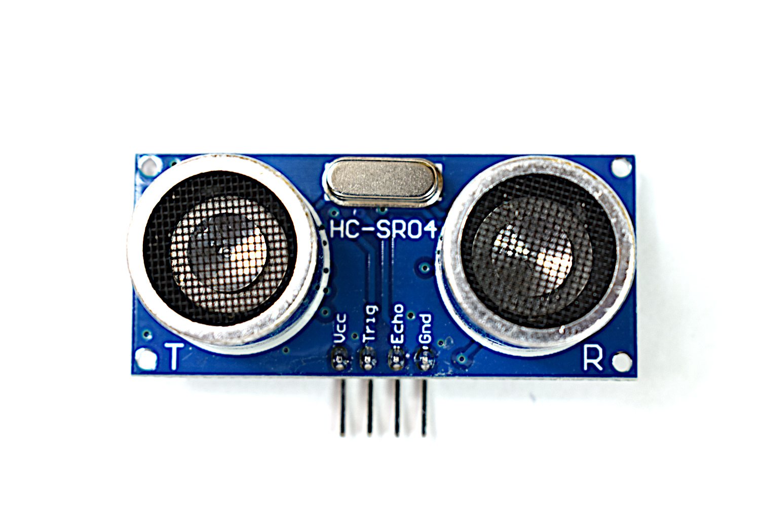
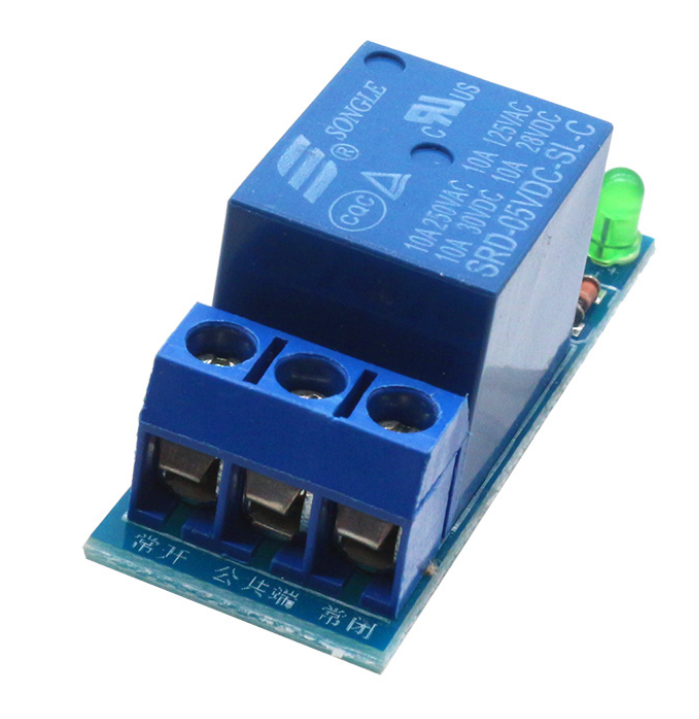
Mount the sensor above a container and measure the air gap to the surface — less gap means more contents. Invert the reading into a percentage, alert when it hits full or empty, and optionally drive a pump through the relay. The practical lesson is calibration: you measure the empty and full distances once and everything else is arithmetic.
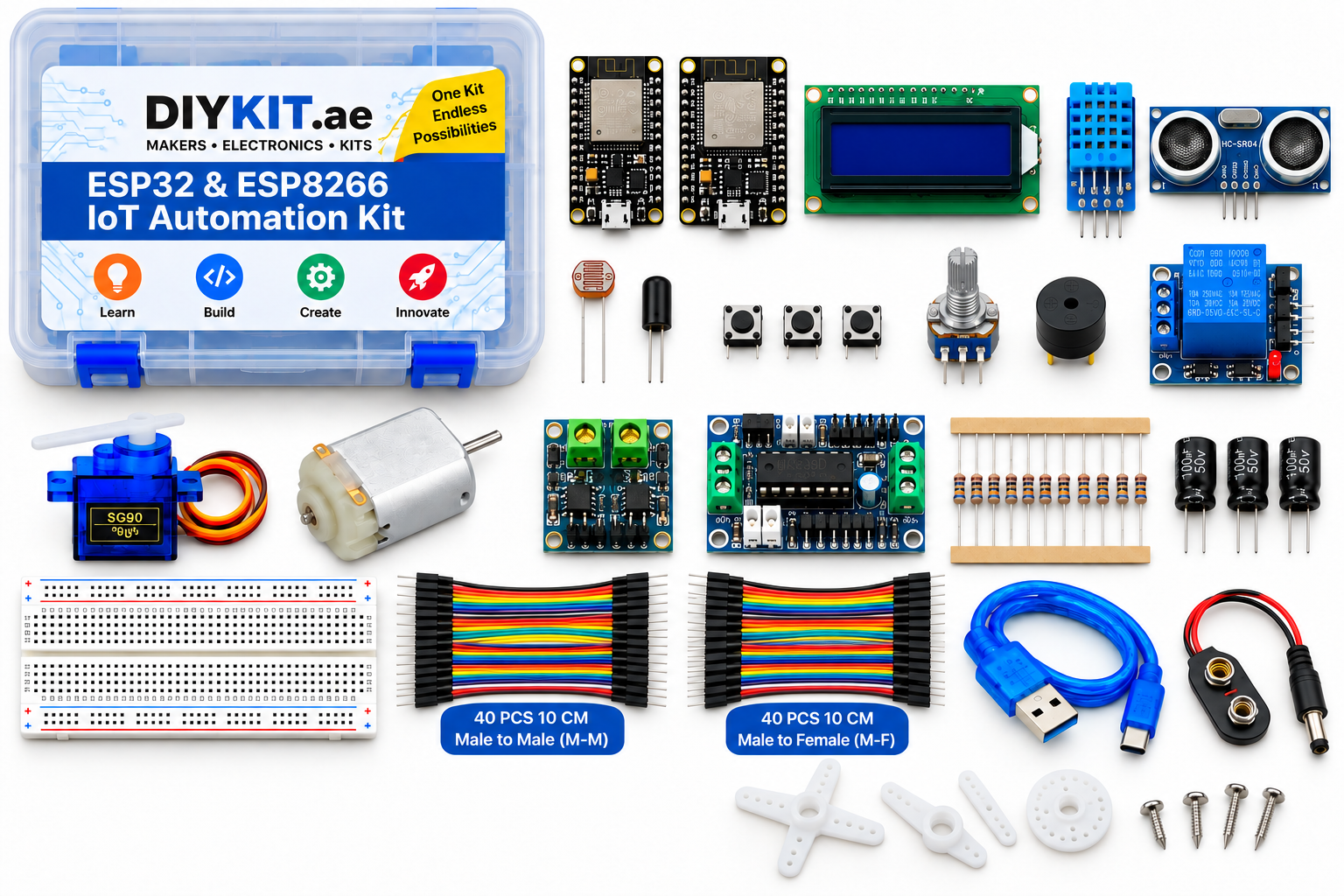
What this project uses
Every item is in the kit — nothing extra to buy.
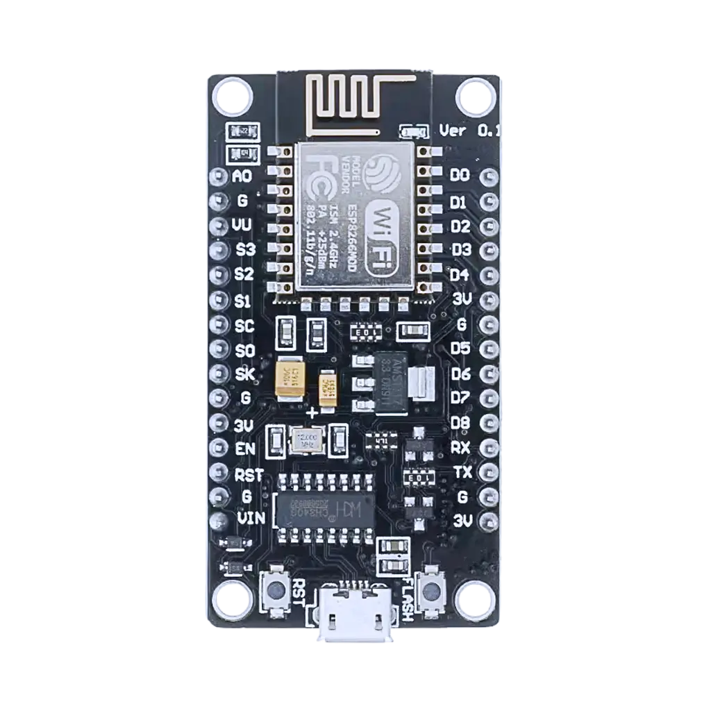



ESP32 & ESP8266 IoT Automation Kit
All 24 parts in one box, with this project and 15 more to build from them.
Need only these parts? Order them loose · from AED 114.84
One of each part. Packs (resistor assortment, jumper wires) already hold more than a single build needs. Backorder parts ship once they arrive — the kit above has every part boxed today. Delivery is free on orders AED 150.00+.
Sketch for this project
Written for the board in the kit. Copy it into the Arduino IDE; change the pin numbers if you wire it differently.
/*
  08 — Tank or bin level monitor
  Board: NodeMCU V3 ESP8266 development board.  Parts: HC-SR04, buzzer module, relay module, 3 x 1 kΩ.

  Wiring:
    HC-SR04: VCC -> VIN (5 V), GND -> GND, TRIG -> D6
             ECHO -> 1 kΩ -> D7, then two 1 kΩ in series from D7 -> GND (5 V -> 3.3 V)
    Buzzer:  VCC -> 3V3, GND -> GND, IO -> D0
    Relay:   VCC -> VIN (5 V), GND -> GND, IN -> D1   (low-level trigger: LOW = on)
             Pump/valve on COM + NO. Low voltage on the bench.

  Mount the sensor above the container looking down. Less air gap = more
  contents. The lesson is calibration: measure EMPTY_CM and FULL_CM once with
  a tape, then everything else is arithmetic.
*/

const int TRIG_PIN   = D6;
const int ECHO_PIN   = D7;
const int BUZZER_PIN = D0;
const int RELAY_PIN  = D1;

const float EMPTY_CM = 60.0;   // sensor to the bottom when empty  <- measure yours
const float FULL_CM  = 8.0;    // sensor to the surface when full   <- measure yours
const int   ALERT_FULL_PCT = 90;
const int   ALERT_EMPTY_PCT = 10;
const bool  PUMP_WHEN_LOW = true;   // set false if the relay drives a drain instead

float readCm() {
  digitalWrite(TRIG_PIN, LOW);  delayMicroseconds(2);
  digitalWrite(TRIG_PIN, HIGH); delayMicroseconds(10);
  digitalWrite(TRIG_PIN, LOW);
  unsigned long us = pulseIn(ECHO_PIN, HIGH, 30000UL);
  return us == 0 ? -1 : us / 58.0;
}

void setup() {
  Serial.begin(115200);
  pinMode(TRIG_PIN, OUTPUT);
  pinMode(ECHO_PIN, INPUT);
  pinMode(BUZZER_PIN, OUTPUT);
  pinMode(RELAY_PIN, OUTPUT);
  digitalWrite(RELAY_PIN, HIGH);   // relay off
}

void loop() {
  float sum = 0; int n = 0;
  for (int i = 0; i < 5; i++) { float d = readCm(); if (d > 0) { sum += d; n++; } delay(30); }
  if (n == 0) { Serial.println("no echo"); delay(500); return; }
  float cm = sum / n;

  // Invert: small gap = full. Clamp to 0..100.
  int pct = (int) (100.0 * (EMPTY_CM - cm) / (EMPTY_CM - FULL_CM));
  pct = constrain(pct, 0, 100);

  bool full  = pct >= ALERT_FULL_PCT;
  bool empty = pct <= ALERT_EMPTY_PCT;
  digitalWrite(BUZZER_PIN, (full || empty) ? HIGH : LOW);

  bool pump = PUMP_WHEN_LOW ? empty : full;
  digitalWrite(RELAY_PIN, pump ? LOW : HIGH);

  Serial.print(cm, 1); Serial.print(" cm  level "); Serial.print(pct); Serial.print(" %  ");
  Serial.println(full ? "FULL" : (empty ? "EMPTY" : "ok"));
  delay(1000);
}More from this kit
Light-triggered night light
The photoresistor forms a voltage divider with a fixed resistor, and the board reads the midpoint on its analog pin. Below a threshold you pick, the relay closes and a l…
Blink and read a button
Both boards carry an onboard LED, so your first sketch needs no wiring at all — blink it, change the timing, watch it obey. Then add a tactile switch to a GPIO pin with…
Read the room
The DHT11 sends both temperature and humidity down a single data wire using its own timing protocol, so a library does the decoding for you. Wire three pins, install the…