Two-board sensor network
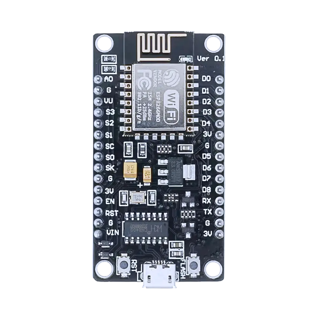
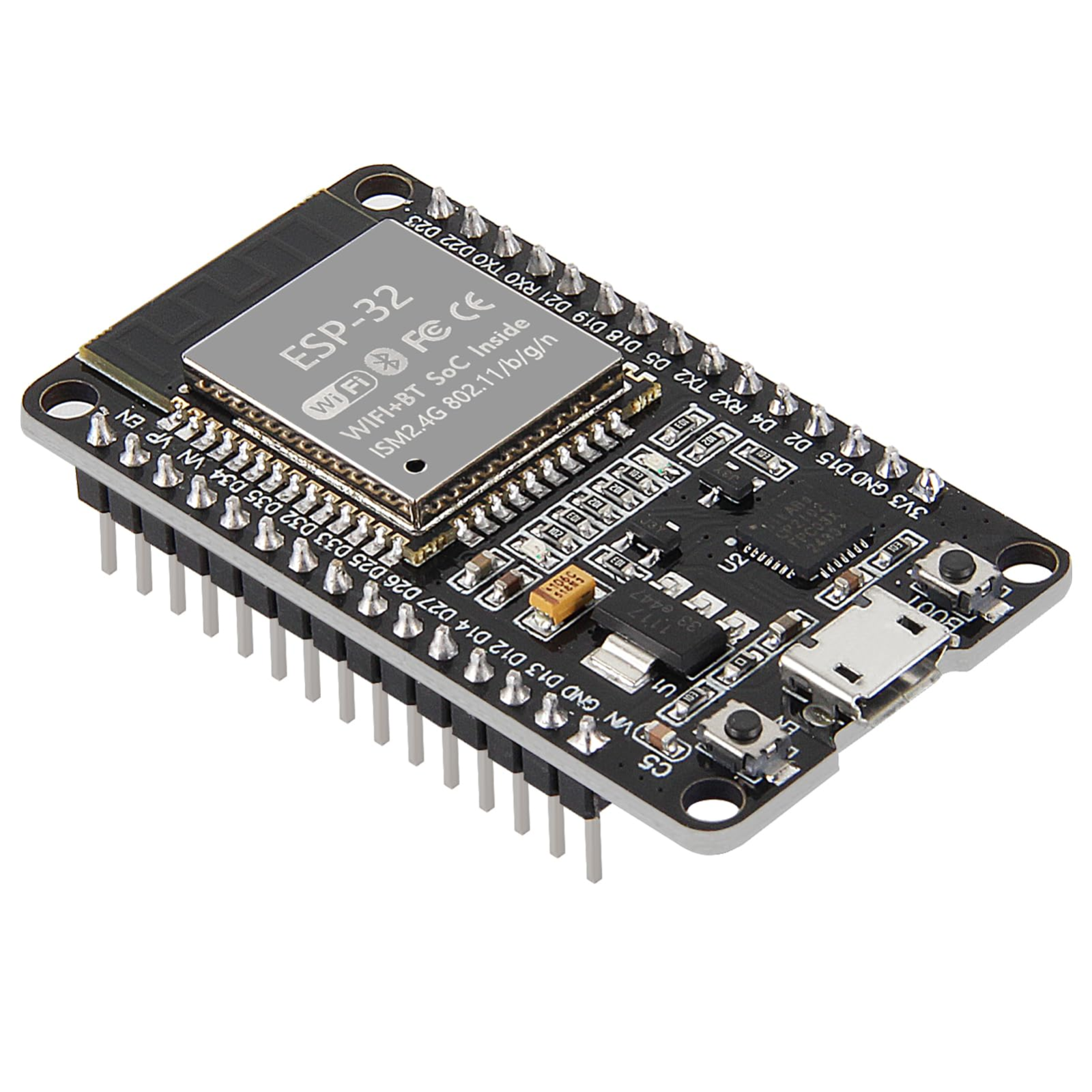
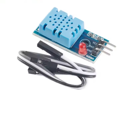
The NodeMCU sits with the sensor and posts its readings over WiFi; the ESP32 receives them and puts them on the LCD. Both boards run at once, so power one from USB and the other from the 9V battery snap, or use two cables. Two devices, one job, and everything that comes with that — what happens when a message is missed, how often to send, what the display should show when the sender goes quiet. This is the first distributed system most people build, and it is the reason the kit ships two boards instead of one.
What this project uses
Every item is in the kit — nothing extra to buy.
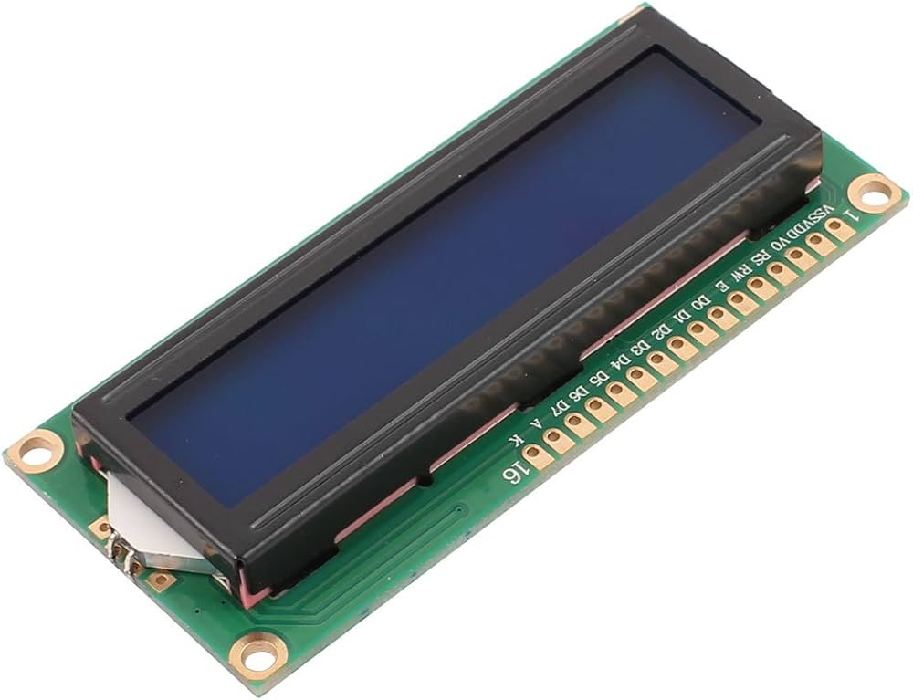
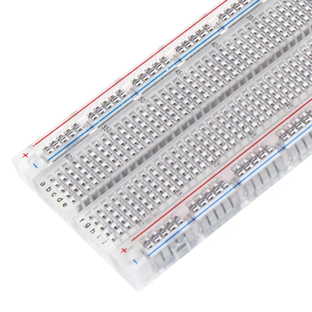


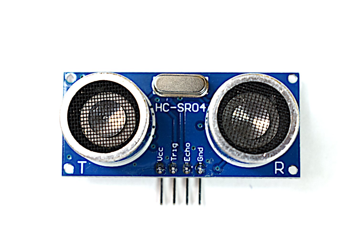

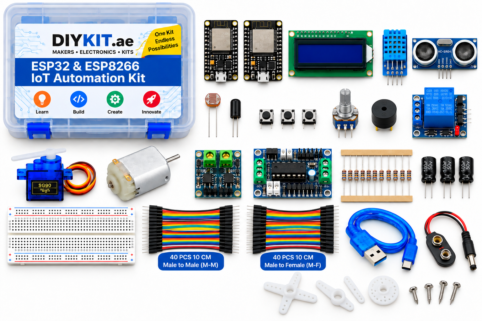
ESP32 & ESP8266 IoT Automation Kit
All 24 parts in one box, with this project and 15 more to build from them.
Need only these parts? Order them loose · from AED 151.46
One of each part. Packs (resistor assortment, jumper wires) already hold more than a single build needs. Backorder parts ship once they arrive — the kit above has every part boxed today. Delivery is free on orders AED 150.00+.
Sketch for this project
Written for the board in the kit. Copy it into the Arduino IDE; change the pin numbers if you wire it differently.
/*
  16 — Two-board sensor network
  Boards: BOTH. One sketch: on the NodeMCU V3 ESP8266 development board it compiles
  as the SENDER (DHT11 -> WiFi), on the ESP32 as the RECEIVER (WiFi -> LCD). Upload it to each board
  with the matching board selected in the IDE. Power both boards at the same time
  from suitable USB power sources; the kit electronics are the two boards, sensors and LCD.
  Libraries: "DHT sensor library" (Adafruit), "LiquidCrystal I2C" (Frank de Brabander).

  Wiring:
    NodeMCU (sender):  DHT11 VCC -> 3V3, GND -> GND, DATA -> D5
    ESP32 (receiver):  LCD VCC -> VIN (5 V), GND -> GND, SDA -> GPIO 21, SCL -> GPIO 22

  Steps: 1) upload to the ESP32 first, read its IP from Serial;
         2) put that IP in RECEIVER_IP below; 3) upload to the NodeMCU.
  Two devices, one job — and what comes with it: a missed message, how often
  to send, what the display shows when the sender goes quiet (here: "no data"
  after 15 s). The first distributed system most people build, and the reason
  the kit ships two boards.
*/

const char* WIFI_SSID   = "YOUR-WIFI-NAME";
const char* WIFI_PASS   = "YOUR-WIFI-PASSWORD";
const char* RECEIVER_IP = "192.168.1.50";        // <- the ESP32's IP from step 1

#if defined(ESP8266)
/* ================= SENDER: NodeMCU + DHT11 ================= */
#include <ESP8266WiFi.h>
#include <ESP8266HTTPClient.h>
#include "DHT.h"

const int DHT_PIN = D5;
DHT dht(DHT_PIN, DHT11);
const unsigned long SEND_EVERY_MS = 5000;

void setup() {
  Serial.begin(115200);
  dht.begin();
  WiFi.mode(WIFI_STA);
  WiFi.begin(WIFI_SSID, WIFI_PASS);
  while (WiFi.status() != WL_CONNECTED) { delay(500); Serial.print("."); }
  Serial.println("\nsender ready");
}

void loop() {
  delay(SEND_EVERY_MS);
  float t = dht.readTemperature(), h = dht.readHumidity();
  if (isnan(t) || isnan(h)) { Serial.println("DHT read failed"); return; }

  WiFiClient client;
  HTTPClient http;
  String url = String("http://") + RECEIVER_IP + "/update?t=" + String(t, 1) + "&h=" + String(h, 0);
  http.begin(client, url);
  int code = http.GET();                      // a missed message just returns an error code
  http.end();
  Serial.print(url); Serial.print(" -> "); Serial.println(code);
}

#elif defined(ESP32)
/* ================= RECEIVER: ESP32 + LCD ================= */
#include <WiFi.h>
#include <WebServer.h>
#include <Wire.h>
#include <LiquidCrystal_I2C.h>

WebServer server(80);
LiquidCrystal_I2C lcd(0x27, 16, 2);
String lastT = "--", lastH = "--";
unsigned long lastSeen = 0;
const unsigned long STALE_MS = 15000;

void setup() {
  Serial.begin(115200);
  lcd.init(); lcd.backlight();
  lcd.print("Joining WiFi...");
  WiFi.mode(WIFI_STA);
  WiFi.begin(WIFI_SSID, WIFI_PASS);
  while (WiFi.status() != WL_CONNECTED) { delay(500); Serial.print("."); }
  Serial.println();
  Serial.print("Receiver IP: "); Serial.println(WiFi.localIP());   // put this in RECEIVER_IP
  lcd.clear(); lcd.print(WiFi.localIP()); lcd.setCursor(0, 1); lcd.print("waiting...");

  server.on("/update", []() {
    lastT = server.arg("t"); lastH = server.arg("h");
    lastSeen = millis();
    server.send(200, "text/plain", "ok");
  });
  server.begin();
}

void loop() {
  server.handleClient();
  static unsigned long lastDraw = 0;
  if (millis() - lastDraw < 500) return;
  lastDraw = millis();

  lcd.setCursor(0, 0);
  lcd.print("T:"); lcd.print(lastT); lcd.print("C H:"); lcd.print(lastH); lcd.print("%   ");
  lcd.setCursor(0, 1);
  if (lastSeen == 0)                       lcd.print("waiting...      ");
  else if (millis() - lastSeen > STALE_MS) lcd.print("no data         ");   // sender went quiet
  else { lcd.print("age "); lcd.print((millis() - lastSeen) / 1000); lcd.print("s        "); }
}

#else
  #error "Select an ESP32 (receiver) or ESP8266 (sender) board"
#endifMore from this kit
WiFi-controlled switch
Join your network, run a small web server on the board, and serve a page with a button that toggles the relay. The board's own IP becomes the address you open from a pho…
Live web dashboard
Serve a page showing temperature, humidity and light level, refreshing on its own so you never reload it. You will meet the reason embedded web work is fiddly: the board…
Blink and read a button
Both boards carry an onboard LED, so your first sketch needs no wiring at all — blink it, change the timing, watch it obey. Then add a tactile switch to a GPIO pin with…