Follow these 7 steps before Lesson 1. They take about 45-60 minutes, most of it the one-time ESP32 download, and prove your computer, cable and ESP32 work - so if something goes wrong later, you know it is the wiring, not the setup.
Lessons 1-4 need only the kit, a computer and a USB-C data cable. Lesson 4 needs the buzzer module, an optional add-on - without it, Lesson 5 still works, silently. Lessons 3 and 5 also need a cushion and a small box or book from home. Lesson 5 is an experiment on a padded bench - never on a person or a wheelchair.
Safety rules for every lesson
This is a learning experiment, not a medical device, wheelchair safety system or emergency alarm. It sends no message and calls no one.
Never attach it to a person or a wheelchair. Test only on a light, padded, unoccupied platform.
Power the ESP32 from USB only. Do not connect batteries or chargers.
Every part in this kit goes to 3V3 - never to 5V or VIN.
Unplug the USB cable before you add, move or remove any wire.
Keep the buzzer away from your ears.
If anything gets hot or smells, or the ESP32 keeps restarting, unplug at once.
Small parts: keep them away from young children. Adult supervision for learners under 12.
1
Check the parts
Open the box and lay the parts out on a clear table.
Tick each one off against the photos and descriptions below.
Safety: Small parts: keep them away from young children and pets.
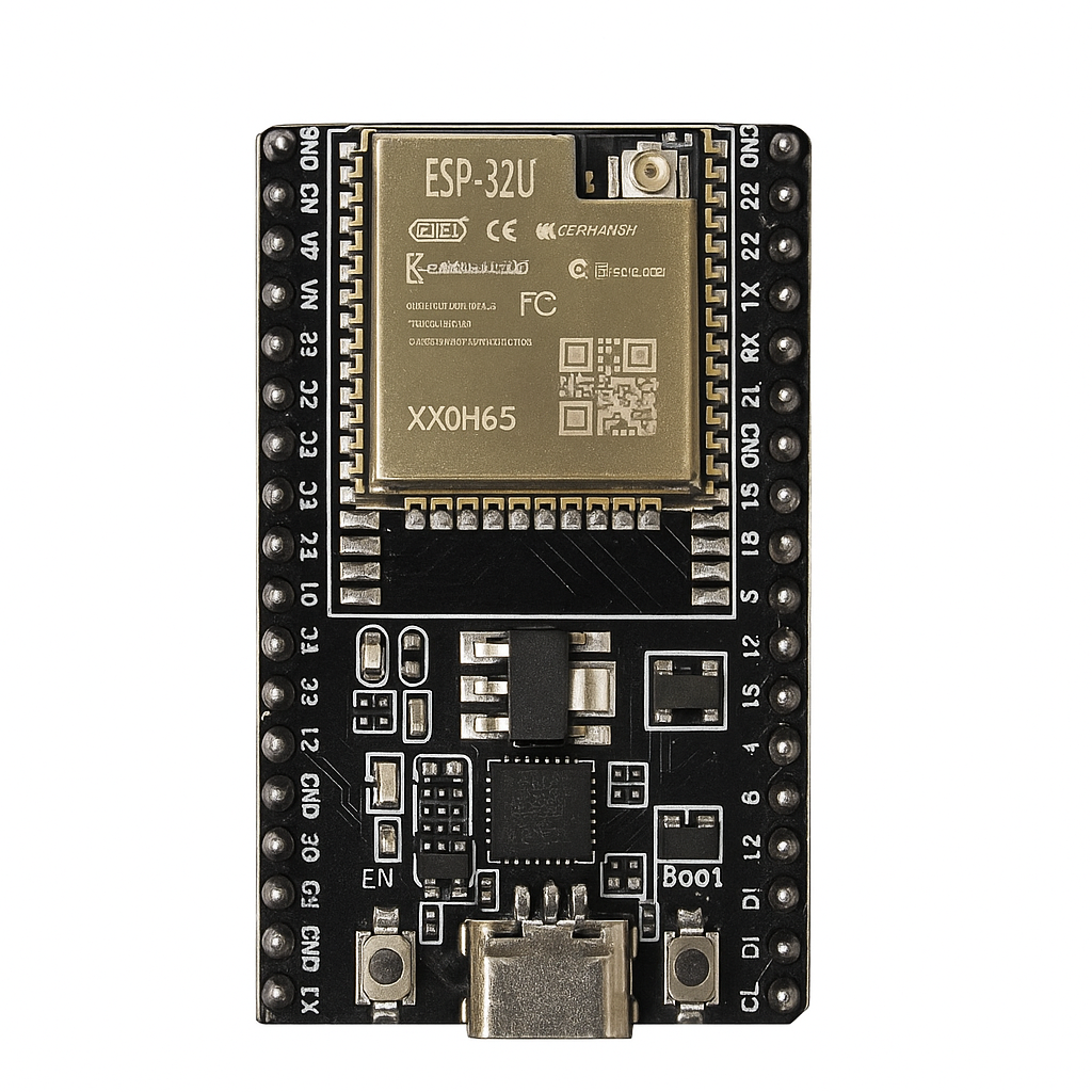
1 × ESP32U DevKitC Type-C - ESP32 WiFi & Bluetooth…ESP32U DevKitC board: a metal-covered ESP32 chip, two rows of pins, a USB-C socket and two small buttons (EN and BOOT).
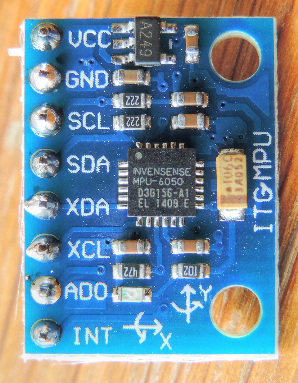
1 × GY-521 MPU-6050 6DOF IMU Sensor Module – 3-Axis…Small blue board marked GY-521 with 8 pins: VCC, GND, SCL, SDA, XDA, XCL, AD0, INT. Its pins may need soldering.
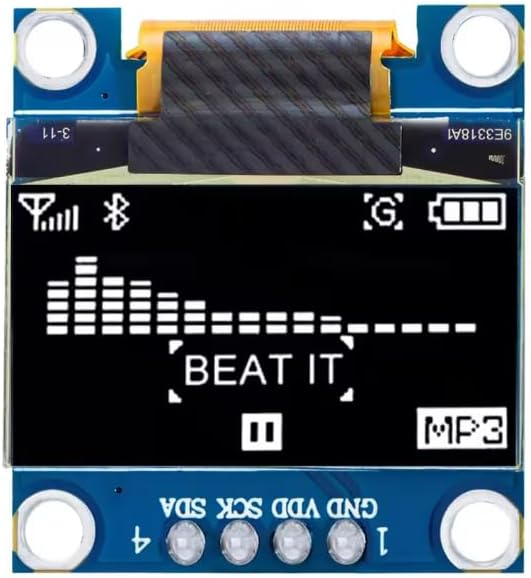
1 × 0.96" OLED Display Module 128x64 I2C (White)Small display with a glass screen and 4 pins labelled GND, VCC, SCL and SDA (the order varies).
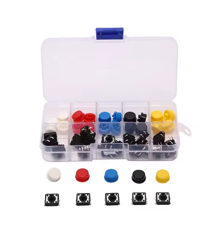
1 × Tactile Microswitch Kit 25pcs 12x12x7.3mm Momen…Box of 25 square push buttons (12 × 12 mm) with coloured caps. Each has 4 legs. The lessons use one.
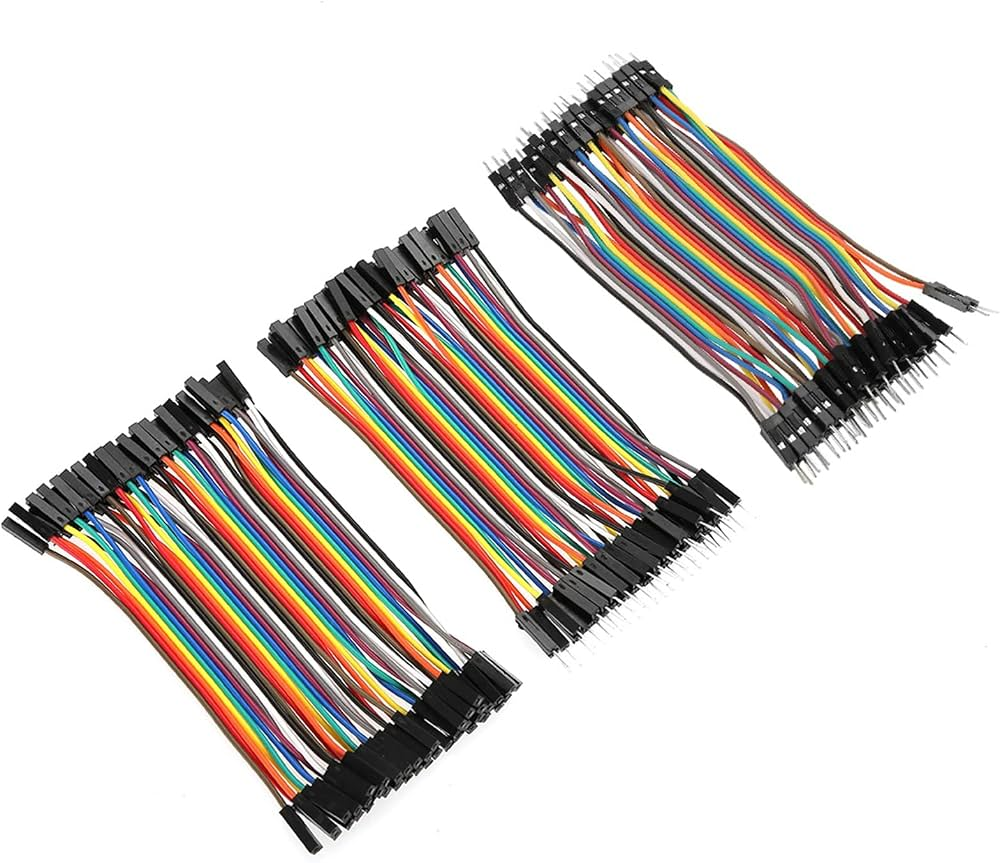
1 × Jumper Wire Assorted Pack 120 Pieces - Male-to-…Rainbow ribbons of 10 cm jumper wires: male-male, male-female and female-female.
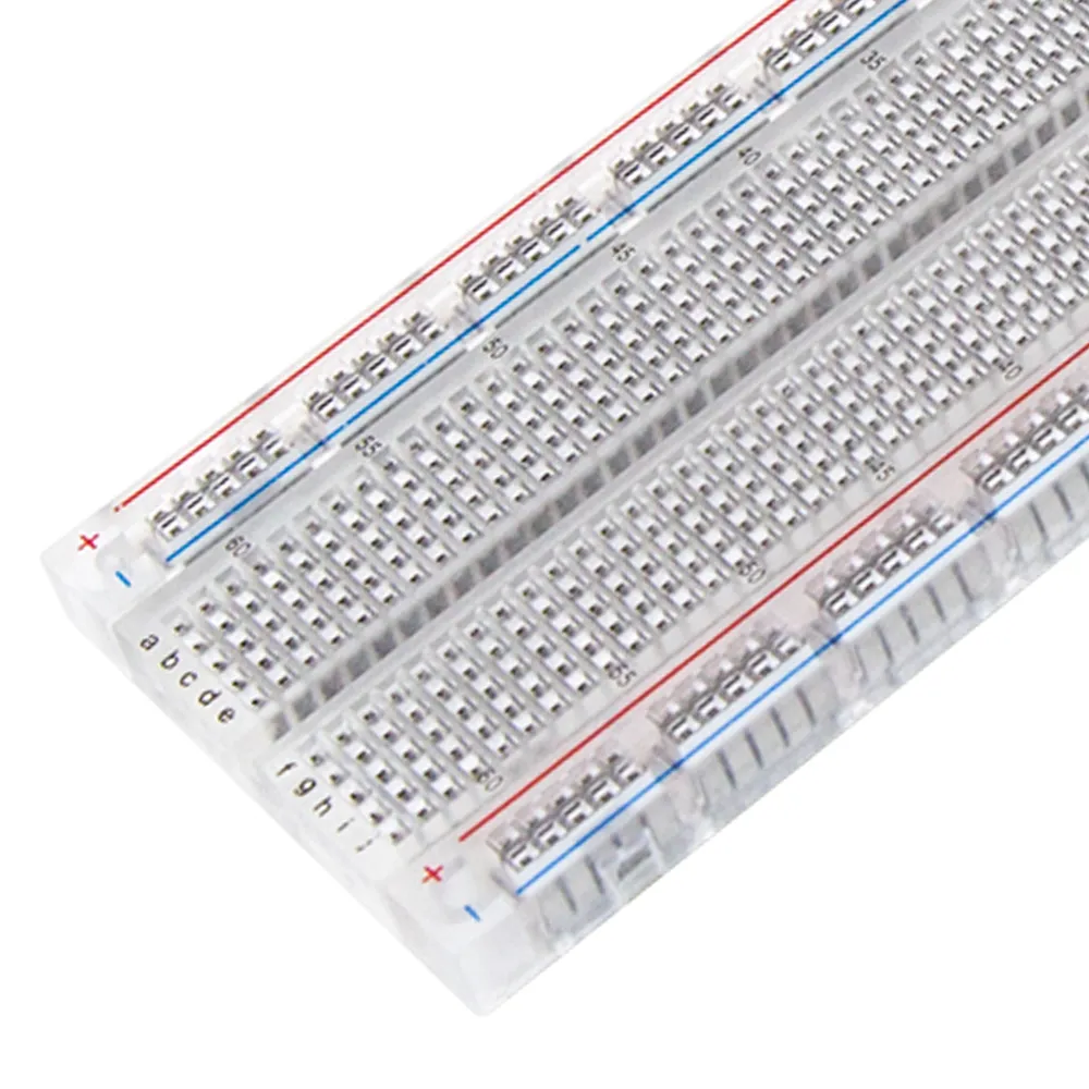
1 × Transparent 830 Points Solderless Breadboard Cl…Clear 830-hole breadboard with red and blue lines along the edges.
Photos are the catalogue pictures of each part. Your parts may differ slightly in colour - go by the shape, the pins and the labels.
You should see: You have the 6 items listed below - plus the buzzer module if you added it (it is optional).
If it doesn't work
Something is missing or broken
Send us a photo with your order number on WhatsApp.
Breadboard
A clear board full of holes that lets you connect parts without soldering.
2
Check what else you need
Read the "You also need" list below.
Find a USB-C data cable for the ESP32, and a computer you are allowed to install software on.
You also need (not in the box)
For
Note
A computer (Windows, macOS or Linux) where you can install the free Arduino IDE 2 and the ESP32 tools
All lessons
A USB-C data cable - not a charge-only cable
All lessons
The ESP32U has a USB-C socket
An internet connection, for the IDE, the ESP32 tools and the libraries
Start here, Lesson 1
A small light box or book, and tape, as a test platform
Lessons 2, 3 and 5
A cushion or foam pad
Lessons 3 and 5
Tests only on a padded, unoccupied platform
Soldering, by an adult
Only if the GY-521 or OLED pins arrive loose
Adult only
A multimeter
Optional
No lesson needs one. Useful for an adult checking 3.3 V and GND.
You should see: You have a computer, a USB-C data cable, an internet connection and an adult nearby.
3
Install the Arduino IDE and the ESP32 tools
Download the free Arduino IDE 2 from arduino.cc/en/software and install it.
Open File → Preferences. In "Additional boards manager URLs" paste: https://espressif.github.io/arduino-esp32/package_esp32_index.json
Open Tools → Board → Boards Manager, search esp32 and install "esp32 by Espressif Systems". It is a big download - allow 10-20 minutes.
You should see: Tools → Board now has an "esp32" section.
If it doesn't work
The download or install is blocked
School and work computers often block installs. Ask an adult or use a home computer.
"esp32 by Espressif Systems" is not listed
Check the Preferences address is pasted exactly, then close and reopen the Boards Manager.
IDE
The program where you write code and send it to the board.
Core
The add-on that teaches the IDE about a type of board, here the ESP32.
4
Connect the ESP32 with a USB-C data cable
Plug the cable into the ESP32 and the computer. Nothing else is connected yet.
Safety: Put the ESP32 on a dry table, away from coins, paper clips and other metal - they can touch the pins underneath and cause a short.
You should see: A small red power light on the ESP32 lights up.
If it doesn't work
No light at all
Push the plug fully in. Try another USB port, then another cable.
5
Select the board and the port
Open Tools → Board → esp32 → ESP32 Dev Module.
Open Tools → Port and choose your ESP32: COM3, COM4… on Windows, /dev/cu.usbserial… or /dev/cu.SLAB… on a Mac, /dev/ttyUSB0 on Linux.
Not sure which one? Unplug the ESP32, look at the list, plug it back in: the new entry is yours.
You should see: The bottom of the IDE window shows "ESP32 Dev Module" and your port.
If it doesn't work
The Port menu is empty
Many USB cables only charge. Use a data cable.
Windows shows an unknown device
Look at the small chip next to the USB socket: CP2102 or CH340. The computer needs the free driver for that chip - ask us on WhatsApp for the link.
Linux: "permission denied" on the port
Ask an adult to add your user to the dialout group (sudo usermod -a -G dialout $USER), then log out and back in.
Port
The name your computer gives the USB connection to the board.
6
Upload a first test
Open File → Examples → ESP32 → ChipID → GetChipID.
Click Upload (→) and wait for "Hard resetting via RTS pin..." or "Done uploading".
Open Tools → Serial Monitor and set the speed to 115200 baud.
You should see: Every 3 seconds the Serial Monitor prints the chip model (ESP32-D0WD…), its revision and the number of cores.
Try it: Change delay(3000) to delay(1000) and upload again. The lines appear every second. Now you know you can change code and upload it.
If it doesn't work
The upload stops at "Connecting....____"
Hold down the BOOT button on the ESP32 when "Connecting" appears, and let go when the percentage starts.
"Failed to connect" or "port is busy"
Close the Serial Monitor and any other program using the port, choose the port again (step 5) and retry.
A red "Compilation error"
Check Tools → Board is ESP32 Dev Module. Close the example without saving and open it again.
The Serial Monitor shows strange symbols
Set the speed to 115200 baud. Press the EN (reset) button to start the sketch again.
Upload
Sending your sketch from the computer into the board. It stays there after you unplug.
Serial Monitor
A window in the IDE (Tools → Serial Monitor) that shows the text the board sends.
7
Continue to Lesson 1
Unplug the USB cable.
Open Lesson 1: Button & OLED Countdown and follow it step by step.
Do the lessons in order: each one builds on the last, and the wiring stays in place.
Still stuck? Ask us on WhatsApp.Send this message with a photo of your wiring - it tells us exactly where you are.
Hi DIY KIT, I'm stuck on the ESP32 Fall-Detection Learning Prototype.
Lesson: __
Step number: __
What should happen: __
What happens instead: __
Error message (copied exactly): __
I'll attach a photo of my wiring.
Put it all together: a jolt or drop followed by staying tipped over starts a beeping 20-second countdown that the button cancels. A learning experiment on the bench - not a safety device.
Start here installs the ESP32 tools. Then 5 lessons build one bench experiment step by step: a button and screen, a tilt angle, jolt and drop data, a buzzer alert (the buzzer is an optional add-on), and finally the fall-detection rule. Every lesson page has a connection diagram, a wiring table, numbered steps, the code, what you should see and a fix-it table.
Start here + 5 lessons6 parts + optional buzzerAbout 4 hoursUSB power onlyLearning experiment - not a safety device
What this kit teaches
Measure · Lessons 2 and 3
Read an accelerometer over I2C, work out a tilt angle from a baseline, and see free fall and impacts in g.
React · Lessons 1 and 4
A debounced button, a countdown on the OLED and a buzzer alert that can be acknowledged and times out.
Decide · Lesson 5
A state machine that needs a jolt and staying tipped over, handles faults clearly, and is tested for false alarms and misses.
Learning experiment only: never attach it to a person or a wheelchair, and never rely on it to detect a fall. It sends no message and calls no one.
The detection rule (Lesson 5)
Step
What must happen
Named in the code
1. Calibrate
Kept still for 3 seconds: the sensor learns "upright"
150 samples
2. Candidate
Total above 2.5 g (jolt) or below 0.45 g (drop)
IMPACT_G, FREEFALL_G
3. Confirm
Within 5 s, tipped more than 55° from upright for 1.5 s
CANDIDATE_MS, TILT_DEG, TILT_HOLD_MS
4. Countdown
20 seconds, a beep each second; the button cancels
COUNTDOWN_MS
5. Local alert
Beeps until the button acknowledges - nothing is sent
-
These are starting values for an experiment, not validated fall criteria.
What the OLED shows
Screen
Meaning
What to do
KEEP STILL AND LEVEL
Learning "upright" for 3 seconds
Do not move the platform
MONITORING
Reading the sensor; shows total g and the event count
Start your controlled tests
POSSIBLE EVENT
The rule matched; the countdown is running
Press the button to cancel
NO EVENT
A jolt or drop, but it did not stay tipped over within 5 seconds
Nothing - monitoring resumes
CANCELLED / ACKNOWLEDGED
You pressed the button
Monitoring resumes
LOCAL ALERT
The countdown ran out
Press to acknowledge - no message was sent
FAULT - POWER OFF
A device is missing, calibration failed or reads failed
Unplug USB and check the wiring
One pin plan
Part
ESP32 pin (printed label)
Lessons
OLED and GY-521 SDA / SCL
GPIO21 / GPIO22
All
OLED, GY-521 and buzzer VCC
3V3 (never 5V)
All
Push button
GPIO26 and GND
All
Buzzer I/O
GPIO27
4, 5
On-board LED (if fitted)
GPIO2
1, 5
Status
All 5 sketches compile for the ESP32 Dev Module (ESP32 core 3.3.11) with no warnings and run in the kit simulator. The complete physical build, the thresholds and the detection have not been bench-tested. Parts may differ slightly from the photos - go by the labels printed on your parts.
// Assembly
Build steps (6)
Tick steps off as you go — your place is kept on this device.
0 / 6
ℹ
These steps come from the build reference recorded for this kit. The firmware is in the Code section below.
// Firmware
Code (5 files)
One sketch per project, written for the boards in this kit. Open a project to read it with its wiring, or copy it there.
ℹ
Pin numbers and thresholds are written for the board in this kit. Change the board and the pin map changes with it — ask and we'll adjust it.
10%// first order
// Welcome
10% off your first order, up to AED 10
Join the build list — new boards, restocks and the occasional teardown.
We'll send your discount code straight away. The code takes 10% off, up to AED 10 on your first order.
// You're on the list
Here's your code
Apply it in the cart before checkout. It also lands in your inbox. Takes 10% off, up to AED 10.
Catalog assistant: verify final stock/price on the product page before checkout.
Cookies on diykit.ae
We use cookies that the shop needs to work — signing in, your cart, form security.
We also measure how the shop is used so we can stock the right parts and fix what is broken.
Choose “Only essential” and we will not load Google Analytics or the Meta pixel, and will not record your visit.
Read more.