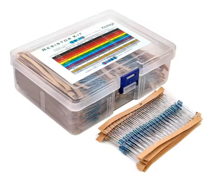
1280 Piece Resistor Kit - 64 Values 1Ω to 10MΩ, 1/4W 1% Metal Film Assortment Box with Colour Code Chart for Arduino, ESP32 & Electronics Projects
- UAE-wide delivery, 1–3 working days · free on orders AED 150+
- Ships today for orders before 3pm
- 7-day returns on unopened items
- SKU
- DIY-345
- Category
- Components
- Brand / MPN
- DIYKIT
- Min. order
- 1 pc
- Barcode
- DKU-000391
A resistor is the cheapest part in any build and the one most likely to stop it. This box carries 20 pieces each of 64 values from 1Ω to 10MΩ — 1280 resistors in total — so the value you need at eleven at night is in the drawer rather than in a supplier's warehouse.
Read the full description ↓64 values, 20 pieces of each. Ohms, kilohms and megohms shown side by side.
| Ohms | Kilohms | Megohms |
|---|---|---|
| 1Ω | 1kΩ | 1MΩ |
| 2.2Ω | 1.5kΩ | 1.5MΩ |
| 4.7Ω | 2.2kΩ | 2MΩ |
| 5.6Ω | 3kΩ | 3.3MΩ |
| 6.2Ω | 3.9kΩ | 4.7MΩ |
| 7.5Ω | 4.7kΩ | 5.6MΩ |
| 10Ω | 5.6kΩ | 10MΩ |
| 15Ω | 6.8kΩ | |
| 22Ω | 7.5kΩ | |
| 27Ω | 8.2kΩ | |
| 33Ω | 10kΩ | |
| 39Ω | 15kΩ | |
| 47Ω | 22kΩ | |
| 56Ω | 33kΩ | |
| 68Ω | 39kΩ | |
| 75Ω | 47kΩ | |
| 82Ω | 56kΩ | |
| 100Ω | 68kΩ | |
| 130Ω | 75kΩ | |
| 150Ω | 82kΩ | |
| 180Ω | 100kΩ | |
| 220Ω | 150kΩ | |
| 270Ω | 180kΩ | |
| 330Ω | 220kΩ | |
| 390Ω | 330kΩ | |
| 470Ω | 470kΩ | |
| 510Ω | 560kΩ | |
| 680Ω | 680kΩ | |
| 820Ω |
29 values below 1kΩ, 28 in the kilohm decade, 7 in the megohm decade.
Description
A resistor is the cheapest part in any build and the one most likely to stop it. This box carries 20 pieces each of 64 values from 1Ω to 10MΩ — 1280 resistors in total — so the value you need at eleven at night is in the drawer rather than in a supplier's warehouse.
Every resistor is 1% metal film on a ceramic substrate with tinned axial leads, sorted into labelled paper strips inside a clear hinged case. A printed 4-band and 5-band colour code chart sits in the lid.
Why 1% metal film
Most starter kits bundle 5% carbon film. That is fine for limiting current through an LED, where nobody can see a 5% difference in brightness. It is not fine when the resistor is setting a reference, dividing a sensor output into an ADC input, or forming an RC time constant — there the tolerance and the temperature coefficient land directly in your measurement.
Metal film also runs quieter. Both types produce the same thermal noise for a given resistance and temperature — that is physics, not construction — but carbon film adds excess current noise on top when current flows through it. In a microphone preamp or a high-impedance sensor front end, that difference is audible and measurable.
Values included
64 values, 20 pieces of each. Ohms, kilohms and megohms shown side by side.
| Ohms | Kilohms | Megohms |
|---|---|---|
| 1Ω | 1kΩ | 1MΩ |
| 2.2Ω | 1.5kΩ | 1.5MΩ |
| 4.7Ω | 2.2kΩ | 2MΩ |
| 5.6Ω | 3kΩ | 3.3MΩ |
| 6.2Ω | 3.9kΩ | 4.7MΩ |
| 7.5Ω | 4.7kΩ | 5.6MΩ |
| 10Ω | 5.6kΩ | 10MΩ |
| 15Ω | 6.8kΩ | |
| 22Ω | 7.5kΩ | |
| 27Ω | 8.2kΩ | |
| 33Ω | 10kΩ | |
| 39Ω | 15kΩ | |
| 47Ω | 22kΩ | |
| 56Ω | 33kΩ | |
| 68Ω | 39kΩ | |
| 75Ω | 47kΩ | |
| 82Ω | 56kΩ | |
| 100Ω | 68kΩ | |
| 130Ω | 75kΩ | |
| 150Ω | 82kΩ | |
| 180Ω | 100kΩ | |
| 220Ω | 150kΩ | |
| 270Ω | 180kΩ | |
| 330Ω | 220kΩ | |
| 390Ω | 330kΩ | |
| 470Ω | 470kΩ | |
| 510Ω | 560kΩ | |
| 680Ω | 680kΩ | |
| 820Ω |
29 values below 1kΩ, 28 in the kilohm decade, 7 in the megohm decade.
The values you will reach for first
| Value | Typical use |
|---|---|
| 220Ω | LED current limiting on a 5V rail |
| 330Ω | LED on 5V, or a dimmer indicator LED |
| 1kΩ | LED on 3.3V; transistor base drive from a GPIO pin |
| 2.2kΩ | I2C bus pull-ups on a short 3.3V bus |
| 4.7kΩ | DS18B20 1-Wire pull-up; standard I2C pull-up |
| 10kΩ | Button pull-up or pull-down; the default for almost everything |
| 1.5kΩ + 3kΩ | Divider dropping a 5V signal to 3.33V for a 3.3V input |
| 100kΩ | High-impedance divider where current draw matters |
| 1MΩ | Input bias for op-amps and high-impedance sensors |
Specifications
| Item | Detail |
|---|---|
| Total pieces | 1280 |
| Values | 64 |
| Pieces per value | 20 |
| Resistance range | 1Ω to 10MΩ |
| Type | Metal film, axial leaded, through-hole |
| Tolerance | ±1% |
| Power rating | 1/4W (0.25W) |
| Lead style | Tinned, 0.1 inch breadboard and PCB compatible |
| Storage | Clear hinged compartment case, one labelled strip per value |
| Included reference | Printed 4-band and 5-band colour code chart |
What it is for
- Current limiting for standard and high-brightness LEDs
- Pull-up and pull-down resistors for buttons, tactile switches and I2C lines
- Voltage dividers scaling a sensor output into a 0–3.3V or 0–5V ADC range
- Base and gate resistors for transistors and MOSFETs driven from a GPIO pin
- RC networks for filtering, switch debouncing and timing
- Op-amp gain and feedback networks where tolerance actually matters
- Repair work, where the value you need is never the one you have
Working with them
Check the power before you check the value. A resistor dissipates V²/R watts, and 1/4W is the ceiling. A 10Ω resistor across 5V burns 2.5W and will scorch — the low-value end of this kit is for current sensing and emitter degeneration, not for dropping a supply rail.
When soldering, leave about 1.5mm between the body and the board so the heat does not travel into the film. Bend the leads with pliers rather than by hand and they will sit flat.
Colour bands are worth learning but not worth trusting on a tired evening. The chart is in the lid; a multimeter is faster, and on a 1% part the fourth and fifth bands are easy to misread under a desk lamp.
Works with
Arduino UNO, Nano and Mega, ESP32, ESP8266, STM32, Raspberry Pi and Pi Pico, and any solderless breadboard, perfboard or through-hole PCB. Nothing in this box is board-specific.
Related components