Overview
The ADXL345 3-Axis Accelerometer Module is a compact MEMS (micro-electro-mechanical systems) sensor breakout designed to measure acceleration along X, Y, and Z axes and deliver the data digitally to a microcontroller. It is widely used for motion detection, tilt sensing, vibration monitoring, and orientation-aware projects. This module integrates the ADXL345 sensor IC on a small PCB with accessible pins for power and communication, making it suitable for breadboards, jumper wires, and embedded prototypes.
Technical Details
ADXL345 is a digital accelerometer that communicates over either I2C or SPI, depending on how the module is wired and how the interface pins are configured. In I2C mode, the sensor is addressed on the bus (exact address selection can depend on the ALT/SDO pin state; check your module’s documentation and the ADXL345 datasheet). In SPI mode, it typically supports 3-wire or 4-wire SPI operation, enabling higher data throughput and deterministic timing for fast sampling applications.
The sensor provides acceleration data through internal registers that can be read at a chosen output data rate (ODR). Many module revisions expose interrupt pins that can be configured to signal events such as activity/inactivity, single/double tap, free-fall, watermark, and data-ready. These features are implemented through on-chip logic and thresholds, reducing the need for constant polling and helping lower system power consumption. Thresholds, durations, and axis participation are configured via registers; real-world tuning is recommended because mechanical mounting, vibration coupling, and enclosure stiffness can strongly affect results.
Power and logic considerations are important for reliable integration. The ADXL345 core is typically a 3.3V device; some breakout boards may include a regulator and/or level shifting, but this varies by module revision. If your module does not include level shifting, use 3.3V logic on I2C/SPI lines or add external level shifters when connecting to 5V microcontrollers. For clean measurements, use stable supply decoupling near the module and keep signal wires short, especially for SPI at higher speeds.
Specifications
- Sensor IC: ADXL345 (3-axis digital MEMS accelerometer)
- Axes: 3 (X, Y, Z)
- Measurement range: commonly selectable up to ±16g (exact selectable ranges and defaults depend on configuration; check datasheet)
- Interface: I2C and/or SPI (availability depends on module revision and pin breakout)
- Logic level: typically 3.3V (some modules may include onboard regulation/level shifting; verify your board)
- Supply voltage: varies by module revision (commonly 3.3V input; some boards accept wider input if regulator is present—confirm before powering)
- Interrupt outputs: may be available (INT1/INT2) depending on module layout
- Mounting: breakout PCB with header pads (header pins may or may not be included; check package)
Applications
- Tilt/orientation sensing for robotics, balancing platforms, and handheld devices
- Vibration and shock monitoring for tools, motors, and equipment health checks
- Motion-triggered wake/sleep systems for battery-powered electronics
- Gesture input, tap detection, and free-fall detection experiments
- Data logging projects with microcontrollers or single-board computers
Integration Notes
- Confirm whether your module includes a voltage regulator and/or level shifting before connecting to 5V systems.
- For I2C, ensure proper pull-up resistors to the correct logic voltage (some boards include pull-ups; others require external pull-ups).
- For SPI, verify whether the module is wired for 4-wire SPI and confirm CS, SCLK, MOSI, MISO pin mapping.
- Use a known-good library for your platform (Arduino/Raspberry Pi/ESP32) and validate readings with a simple static test (gravity vector) before deploying.
- Mechanical mounting affects readings; rigid mounting reduces resonance and improves repeatability.
Included Components
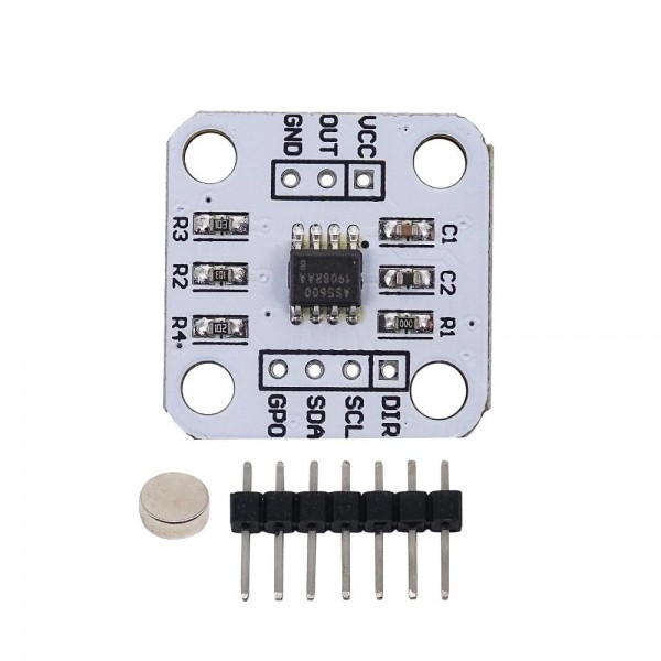
ADXL345 3-Axis Accelerometer Module x1





![Temperature sensor [TMP36]](https://diykit.ae/uploads/products/1783496467_29c5e5faceee15fbbda9-w320.webp)

