L298N Dual H-Bridge Motor Driver Module, DC Motor & Stepper Controller Board for Arduino & DIY Robotics
Generic Verified listing

L298N Dual H-Bridge Motor Driver Module, DC Motor & Stepper Controller Board for Arduino & DIY Robotics

SKU: DIY-00093
Ask for price
In stock · 9 units Ships from Dubai
Find similar
Ask for price — add to quote for a quotation.
Free delivery Orders over AED 100
Returns policy 14-day returns if unused
Tech help Wiring & code support
More options
Free shipping on orders AED 100+. Below that: AED 25.

Control motors confidently in your robotics and automation builds with the L298N motor driver module, a popular dual H-bridge driver board designed to run two DC motors independently or drive one bipolar stepper motor. This module is widely used in Arduino and DIY robotics because it provides a simple way to control motor direction and speed using standard digital pins and PWM. Whether you’re building a 2WD/4WD robot car, a small conveyor prototype, an actuator controller, or a motion-based experiment, the L298N board is a practical and proven motor control solution.

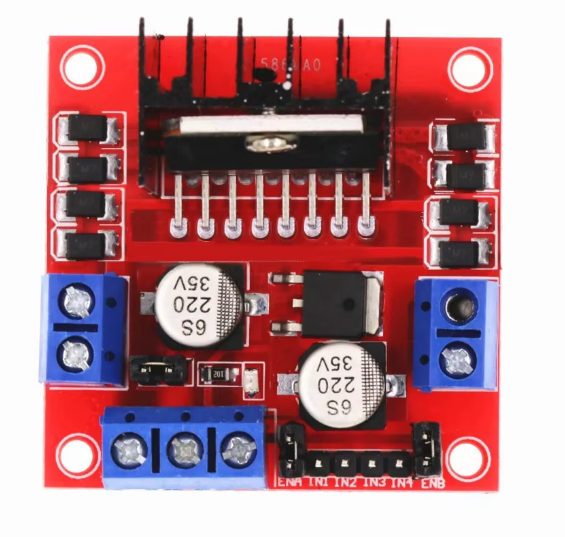
The module uses the L298N dual full-bridge driver IC and typically includes a heatsink to help manage heat during operation. With two channels (A and B), you can connect two separate DC motors and control each motor’s direction using IN pins (IN1–IN4). Speed control is usually achieved by applying PWM signals to ENA and ENB (enable) pins. This gives you flexible control for robotics: forward/reverse, turning, braking, and speed adjustment. For stepper motors, the board can drive a bipolar stepper by controlling the coil pairs through the two H-bridges, making it useful for simple positioning projects and educational demonstrations.

Specifications (typical for L298N modules)

  • Driver IC: L298N dual H-bridge
  • Motor channels: 2 (DC motors) or 1 (bipolar stepper)
  • Motor supply voltage (Vs): typically 5V to 35V input (module dependent)
  • Logic voltage: 5V logic input (TTL compatible)
  • Output current: up to 2A per channel peak (practical continuous current is usually lower; use heatsinking and airflow)
  • Control pins: ENA, IN1, IN2 (Motor A) and ENB, IN3, IN4 (Motor B)
  • Terminals: screw terminals for Motor A/B outputs and power input
  • Onboard 5V regulator: commonly included (use only when input voltage is suitable and jumper/regulator is enabled)
  • Protection/notes: voltage drop across driver is normal for this IC; motor sees less than supply voltage under load

Because the L298N is a classic bipolar transistor-based driver, it has a voltage drop that reduces the effective motor voltage compared to the supply. This is normal behavior and is important to consider if you need maximum motor speed or torque. For best results, use a motor supply that matches your motor requirements and allow for this drop. Also, motor drivers can get hot under load—especially at higher currents—so it’s good practice to ensure adequate ventilation and avoid exceeding the practical continuous current limit.

Wiring is straightforward. Connect your motor power supply to the input terminals, connect your motors to the output terminals, and connect the control pins to your microcontroller. Always share ground between the motor driver and your controller. If you plan to power the microcontroller from the module’s 5V output, confirm the regulator configuration and ensure the input voltage range is appropriate. In many builds, it’s safer to power the controller separately and use the driver only for motor power switching.

This L298N module is ideal for learning motor control, prototyping robot movement, and building reliable DIY motion projects. With screw terminals, clear pin labeling, and flexible control using PWM, it’s a go-to driver board for makers who want simple and effective dual motor control.

Included Components

1× L298N motor driver module with heatsink

Full description

Control motors confidently in your robotics and automation builds with the L298N motor driver module, a popular dual H-bridge driver board designed to run two DC motors independently or drive one bipolar stepper motor. This module is widely used in Arduino and DIY robotics because it provides a simple way to control motor direction and speed using standard digital pins and PWM. Whether you’re building a 2WD/4WD robot car, a small conveyor prototype, an actuator controller, or a motion-based experiment, the L298N board is a practical and proven motor control solution.

The module uses the L298N dual full-bridge driver IC and typically includes a heatsink to help manage heat during operation. With two channels (A and B), you can connect two separate DC motors and control each motor’s direction using IN pins (IN1–IN4). Speed control is usually achieved by applying PWM signals to ENA and ENB (enable) pins. This gives you flexible control for robotics: forward/reverse, turning, braking, and speed adjustment. For stepper motors, the board can drive a bipolar stepper by controlling the coil pairs through the two H-bridges, making it useful for simple positioning projects and educational demonstrations.

Specifications (typical for L298N modules)

  • Driver IC: L298N dual H-bridge
  • Motor channels: 2 (DC motors) or 1 (bipolar stepper)
  • Motor supply voltage (Vs): typically 5V to 35V input (module dependent)
  • Logic voltage: 5V logic input (TTL compatible)
  • Output current: up to 2A per channel peak (practical continuous current is usually lower; use heatsinking and airflow)
  • Control pins: ENA, IN1, IN2 (Motor A) and ENB, IN3, IN4 (Motor B)
  • Terminals: screw terminals for Motor A/B outputs and power input
  • Onboard 5V regulator: commonly included (use only when input voltage is suitable and jumper/regulator is enabled)
  • Protection/notes: voltage drop across driver is normal for this IC; motor sees less than supply voltage under load

Because the L298N is a classic bipolar transistor-based driver, it has a voltage drop that reduces the effective motor voltage compared to the supply. This is normal behavior and is important to consider if you need maximum motor speed or torque. For best results, use a motor supply that matches your motor requirements and allow for this drop. Also, motor drivers can get hot under load—especially at higher currents—so it’s good practice to ensure adequate ventilation and avoid exceeding the practical continuous current limit.

Wiring is straightforward. Connect your motor power supply to the input terminals, connect your motors to the output terminals, and connect the control pins to your microcontroller. Always share ground between the motor driver and your controller. If you plan to power the microcontroller from the module’s 5V output, confirm the regulator configuration and ensure the input voltage range is appropriate. In many builds, it’s safer to power the controller separately and use the driver only for motor power switching.

This L298N module is ideal for learning motor control, prototyping robot movement, and building reliable DIY motion projects. With screw terminals, clear pin labeling, and flexible control using PWM, it’s a go-to driver board for makers who want simple and effective dual motor control.

Included Components

1× L298N motor driver module with heatsink
Customer reviews

No reviews yet — be the first.

Honest takes from buyers who built with this part.

Write a review

Customer Q&A

No questions yet.

Ask anything — the team and other customers will reply.

No questions yet. Be the first to ask — useful answers help other buyers too.

Ask a question

Starter Bundle Builder

Select compatible items and add all selected products in one click.
4 compatible items
View cart

Works With

Find more compatible parts

Related

TurtleBot 4
Backorder
CLEARPATH DIY-168
TurtleBot 4
TurtleBot 4 is the next-generation of the world’s most popular open source robotics platform for education and resear...
AED 7,254.12