Overview
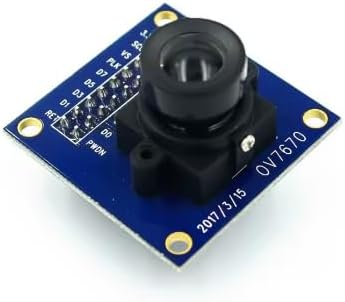
The OV7670 camera module is a compact VGA image sensor board designed for microcontroller and embedded systems that need low-cost image capture. It integrates an OV7670 CMOS sensor and a fixed-focus lens on a small PCB, exposing a parallel digital video port (DVP) for pixel data plus a simple control bus for register configuration. This makes it a popular choice for Arduino-compatible development, STM32/ESP32 camera experiments (where parallel camera input is supported), FPGA video pipelines, robotics vision prototypes, and basic machine-vision learning projects where VGA resolution is sufficient.
Technical Details
This module outputs pixel data over an 8-bit parallel bus (D0–D7). In addition to the data lines, the sensor provides timing signals typically including PCLK (pixel clock), VSYNC (frame sync), and HREF/HSYNC (line valid, naming varies by module/silkscreen). The sensor is configured via SCCB, which is compatible in practice with I2C-style signaling (device address and register map per OV7670 datasheet). Through register configuration you can select resolution scaling, color space, output packing (for example RGB565), automatic exposure control, automatic gain control, white balance, and other image processing features available in the sensor.
Because the OV7670 streams data continuously when enabled, most 8-bit Arduino boards cannot capture full frames without external FIFO/RAM or a dedicated capture interface. Typical approaches include: capturing small windows/low frame rates, using a microcontroller with camera interface/DMA, adding an external FIFO buffer board, or using an FPGA/CPLD to latch and store frames. Power and logic levels are also important: the sensor core and I/O are commonly 3.3V. Some module revisions include an onboard 3.3V regulator for the power pin, but the data/control I/O still generally expects 3.3V logic. If you are using a 5V microcontroller, use proper level shifting (especially for SCL/SDA and any input clocks) and ensure the module’s output high level is compatible with your MCU’s input threshold.
Specifications
- Sensor model: OV7670 (module revision and lens variant may vary)
- Maximum resolution: VGA 640 x 480 (as commonly supported by OV7670; confirm in datasheet)
- Data interface: 8-bit parallel DVP (D0–D7) plus sync/clock signals (exact pin naming varies by board)
- Control interface: SCCB (I2C-compatible) for register configuration
- Output formats: configurable; commonly RGB565, YUV/YCbCr, and Bayer RAW (depends on register settings; check datasheet)
- Supply voltage: typically 3.3V required by sensor; some boards may accept a higher input via onboard regulator (varies by module revision—verify PCB markings)
- Logic level: typically 3.3V I/O (level shifting recommended for 5V systems)
- Lens: fixed-focus lens installed (FOV and focal length vary by module revision)
- Mounting: PCB mounting holes (count/spacing varies by board layout)
Applications
- DIY embedded camera projects and learning image sensor interfacing
- Robotics line tracking, simple object detection, and vision-assisted navigation (with appropriate processing hardware)
- FPGA video capture and image processing pipelines
- Microcontroller camera experiments with DMA/parallel camera peripherals
- Educational projects demonstrating SCCB/I2C register control and parallel video timing
Integration Notes
- Pinout differs between board revisions; always confirm the silkscreen labels and compare with the OV7670 reference pin functions before wiring.
- Many Arduino UNO/Nano-class boards lack RAM and bandwidth for full VGA frame buffering. For full-frame capture, consider an external FIFO module, a higher-end MCU with camera interface, or an FPGA.
- Keep wiring short and tidy for PCLK and data lines to reduce noise and timing errors. Use a solid ground reference.
- If your host is 5V logic, use level shifters for inputs to the camera (SCL/SDA, XCLK if provided) and confirm that camera outputs meet your MCU input thresholds.
- Use the OV7670 datasheet/register guide for correct initialization sequences and format selection.
Included Components
1x OV7670 Camera Module (VGA sensor board)