 Backorder
4 Channel Relay Module, DC 5V, High/Low Level Trigger, Optocoupler Shield for Arduino
Overview This 4 Channel Relay Module (DC 5V) is designed to let low-voltage controllers switch higher-voltage or higher-current loads safely and reliably using electromechanical relays.
Overview
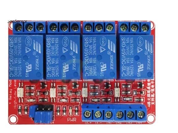
This 4 Channel Relay Module (DC 5V) is designed to let low-voltage controllers switch higher-voltage or higher-current loads safely and reliably using electromechanical relays. It is commonly used with Arduino, Raspberry Pi, ESP32, and other DIY control platforms for home automation, robotics power routing, test fixtures, and general-purpose switching. The board shown uses four blue Songle-style relays and provides screw terminals for both the load side (COM/NO/NC) and the control/power side, making it practical for prototyping as well as semi-permanent installations.
Technical Details
Each relay channel is driven by an onboard interface circuit that typically includes an optocoupler (for input isolation), a transistor driver stage, and a flyback diode path to manage coil inductive kick. The optocoupler stage helps decouple noisy load-side transients from the logic side, improving stability when switching inductive loads such as solenoids, contactors, small motors, or valves.
The module accepts a 5V DC supply for the relay coils. Control inputs are provided via header pins/screw terminals (layout varies by revision). Many versions include a jumper or selector that enables either LOW-level trigger (active-low) or HIGH-level trigger (active-high). Because trigger selection and input circuitry can differ between revisions, confirm the exact behavior by checking the silkscreen labels and/or the module datasheet before final wiring.
On the output side, each relay exposes three terminals: COM (common), NO (normally open), and NC (normally closed). With the relay de-energized, COM is connected to NC. When energized, COM switches to NO. This allows you to implement fail-safe behaviors (using NC) or default-off behaviors (using NO) depending on your application.
Specifications
- Relay channels: 4
- Relay coil supply: DC 5V (module powered)
- Trigger mode: High/Low level trigger (selection varies by module revision; verify on board)
- Isolation: Optocoupler input stage (implementation varies by revision; verify component markings)
- Output contacts per channel: COM, NO, NC (screw terminals)
- Typical relay contact rating (as marked on many Songle relays pictured): up to 10A @ 250VAC, 10A @ 30VDC (always confirm printed relay rating and derate for inductive loads)
- Indicators: Power LED and per-channel relay status LEDs (typical)
- Wiring interface: Screw terminals for load outputs and power/control (exact terminal grouping varies by revision)
- Compatible controllers: Arduino, Raspberry Pi (via suitable GPIO level/interface), ESP32, STM32, and other MCU boards (ensure proper logic level compatibility)
Applications
- Home automation: switching lights, fans, pumps, heaters (with appropriate electrical protection)
- Robotics and DIY machines: power routing to motors, actuators, and auxiliary subsystems
- Test benches: automated power cycling, load selection, and fixture control
- Security and access projects: controlling strikes, buzzers, sirens (use proper suppression for inductive loads)
- Energy projects: switching DC loads such as LED strips or small DC power rails within rated limits
Integration Notes
- Power: Provide a stable 5V DC supply capable of handling relay coil current for multiple channels; current draw depends on relay coil specs and how many channels are active simultaneously (check relay datasheet/label).
- Logic levels: If using 3.3V GPIO (e.g., Raspberry Pi/ESP32), verify the input threshold and trigger mode. Some revisions work directly; others may require a transistor/level-shift stage for reliable switching.
- Safety: Mains AC wiring must be done with proper insulation, strain relief, fusing, and enclosure. Keep low-voltage control wiring separated from high-voltage load wiring.
- Inductive loads: Use snubbers/RC networks for AC loads or flyback diodes/TVS for DC loads where appropriate to reduce arcing and extend relay life.
- Contact derating: The printed 10A rating is typically for resistive loads; inductive loads should be derated significantly. Always validate with your load type and duty cycle.
Included Components: 4-Channel 5V Relay Module with Optocoupler (1pc)
No reviews for this component yet.
Related Components