Lesson 1: LED Basics & Brightness
Make an LED blink, then turn a knob to fade it from off to full brightness. You will learn how to wire an LED safely and how the UNO can dim a light.
Before you start
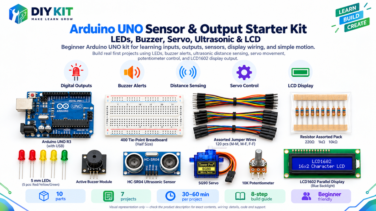
Exact parts
| Part | How many |
|---|---|
| UNO R3 + USB cable | 1 |
| 400-point breadboard | 1 |
| Yellow LED | 1 |
| 220 Ω resistor (red-red-brown) | 1 |
| 10K potentiometer | 1 |
| Male-to-male jumper wires | about 7 |
Not in the box
Nothing extra - just the kit and your computer.
What you build and learn
- Which LED leg is + and which is −
- Why every LED needs a resistor
- digitalWrite(): switching a pin on and off
- analogRead() and analogWrite(): reading a knob and dimming a light
An LED only works one way round: current goes in through the long leg (+) and out through the short leg (−). On its own it would take too much current, so a 220 Ω resistor always goes in line with it to protect the LED and the UNO pin.
digitalWrite(3, HIGH) puts 5 volts on pin 3 and the LED lights. LOW turns it off. That is how the 3 blinks at the start work.
The potentiometer is a knob. Its middle pin gives a voltage between 0 and 5V depending on how far you turn it, and analogRead(A0) turns that into a number from 0 to 1023.
The UNO cannot make "half a volt". Instead analogWrite() switches pin 3 on and off very fast (PWM). On for half the time looks half as bright. 0 is off, 255 is full brightness.
New words
- Breadboard
- A board with hidden metal strips inside. Parts pushed into the same short row of holes are connected to each other.
- Rail
- The long lines of holes along the edge of the breadboard. We use the red line (+) for 5V and the blue line (−) for GND.
- GND
- Ground: 0 volts. Every circuit needs a way back to GND.
- Resistor
- A part that limits current. 220 Ω has the colour bands red-red-brown.
- Pin
- A numbered connection on the UNO's black header strips, like pin 3 or A0.
- PWM
- Switching a pin on and off very fast. Pins with a ~ mark can do it, and it makes an LED look dimmer.
What this project uses
Every item is in the kit — nothing extra to buy.

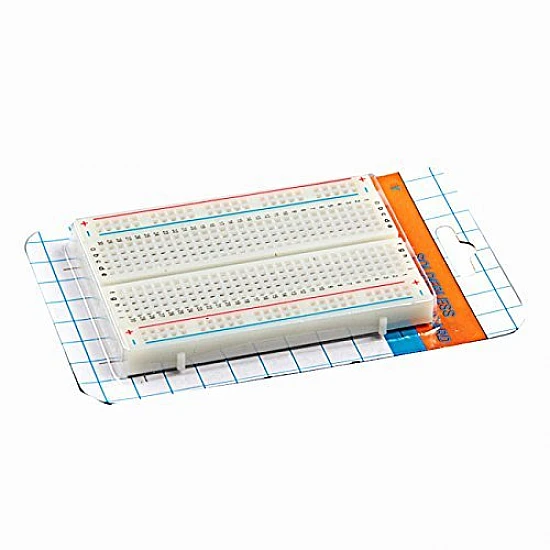
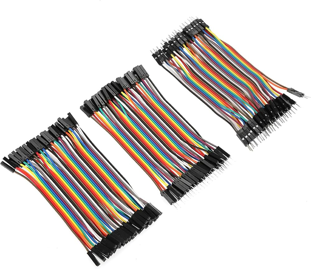
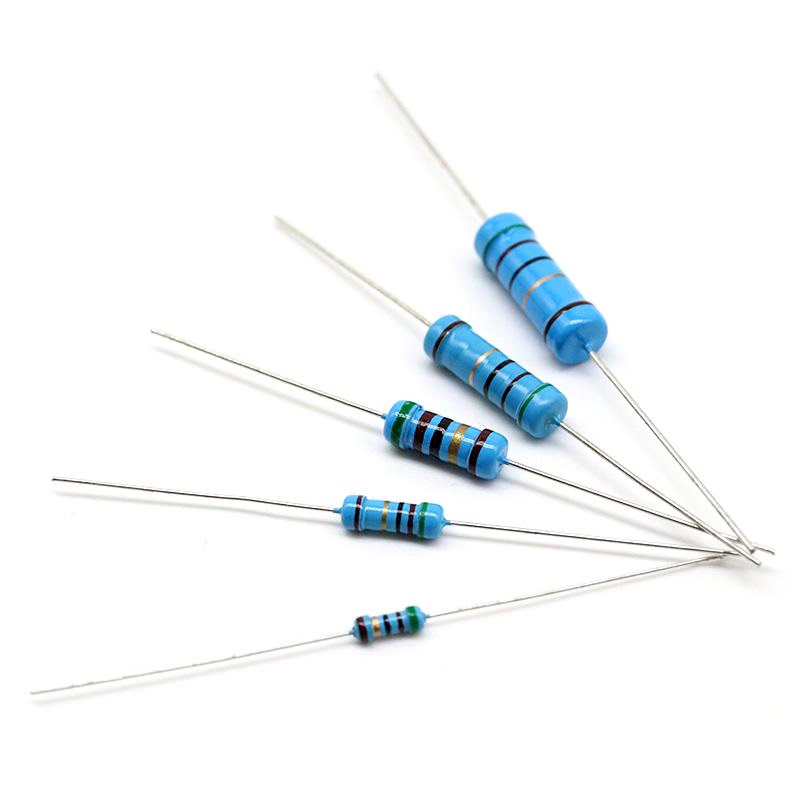
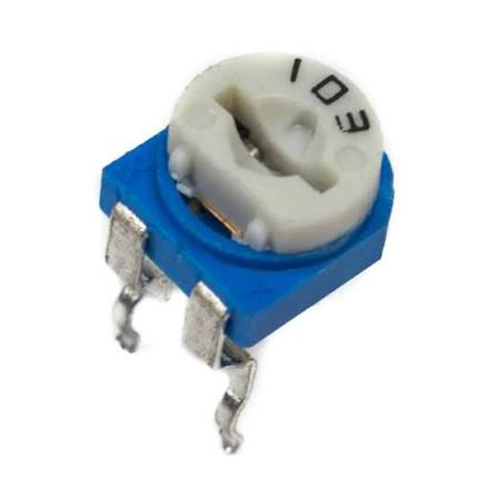
Arduino UNO Sensor & Output Starter Kit - LEDs, Buzzer, Servo, Ultrasonic & LCD
All 10 parts in one box, with this project and 6 more to build from them.
Need only these parts? Order them loose · from AED 110.05
One of each part. Packs (resistor assortment, jumper wires) already hold more than a single build needs. Delivery is AED 20, free on orders AED 100+.
Connections
Unplug USB before you change any wire. Pin names are the labels printed on the board.
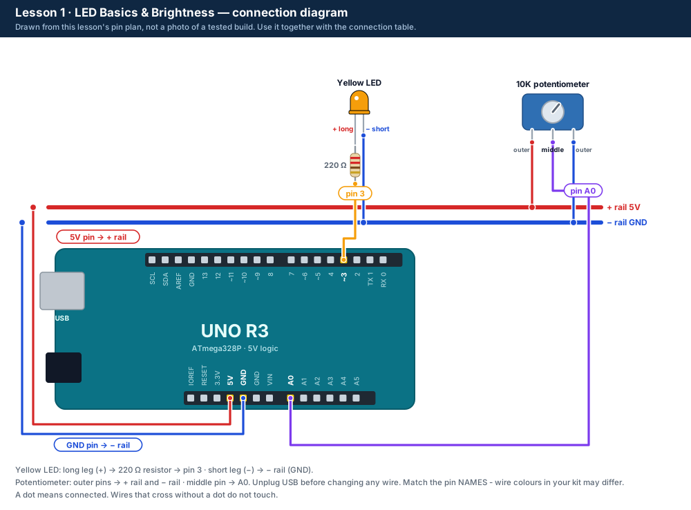
| Part / pin | Connect to | Note |
|---|---|---|
| UNO 5V | + rail (red line) | Powers the knob |
| UNO GND | − rail (blue line) | Shared ground for everything |
| UNO pin 3 | 220 Ω resistor → yellow LED long leg (+) | Pin 3 has a ~ mark, so it can dim |
| Yellow LED short leg (−) | − rail (GND) | |
| Potentiometer outer pin | + rail (5V) | Either outer pin |
| Potentiometer other outer pin | − rail (GND) | |
| Potentiometer middle pin | UNO A0 | On the lower header, by ANALOG IN |
Step by step
One thing at a time. Tick nothing off until it matches the diagram.
- Unplug the USB cable from the computer.Watch out: Always unplug the USB cable before you add, move or remove a wire.
- Put the breadboard next to the UNO. Find the red (+) and blue (−) lines along its edge: those are the rails.
- Connect a jumper wire from the UNO 5V pin to the + rail, and one from a UNO GND pin to the − rail.
- Push the yellow LED into the breadboard so its two legs are in two different rows. Remember which row has the long leg.Watch out: The long leg is +. If the legs have been cut, look for the flat edge on the LED's rim: that side is −.
- Push one end of a 220 Ω resistor (red-red-brown) into the long-leg row and the other end into an empty row.Watch out: Every LED needs its resistor. Without it the LED or the UNO pin can be damaged.
- Connect a jumper wire from that empty row to UNO pin 3.
- Connect a jumper wire from the LED's short-leg row to the − rail.
- Push the potentiometer into the breadboard. Wire one outer pin to the + rail, the other outer pin to the − rail and the middle pin to A0.
- Check every wire against the diagram and the table, then plug the USB cable back in.Watch out: If anything gets hot or smells, unplug straight away.
- Copy the Lesson 1 code below into the Arduino IDE and click Upload (→).
- Watch the LED blink 3 times, then turn the knob slowly from one end to the other.
Sketch for this project
Written for the board in the kit. Copy it into the Arduino IDE; change the pin numbers if you wire it differently.
/*
  DIY KIT - Arduino UNO Sensor & Output Starter Kit
  Lesson 1 of 7: LED Basics & Brightness

  WIRING (unplug the USB cable before you wire)
    Yellow LED long leg (+)  -> 220 ohm resistor -> UNO pin 3
    Yellow LED short leg (-) -> GND
    Potentiometer outer pins -> 5V and GND (either way round)
    Potentiometer middle pin -> UNO pin A0

  WHAT SHOULD HAPPEN
    1. The LED blinks 3 times. That proves the LED is wired the right way.
    2. Then turn the knob: the LED fades from off to fully bright.
*/

const int LED_PIN  = 3;    // the yellow LED. Pin 3 has a ~ mark, so it can dim (PWM)
const int KNOB_PIN = A0;   // the middle pin of the potentiometer
const int BLINK_MS = 300;  // how long each start-up blink lasts, in milliseconds

void setup() {
  pinMode(LED_PIN, OUTPUT);   // pin 3 sends power OUT to the LED
  Serial.begin(9600);         // talk to the computer (Serial Monitor at 9600 baud)
  Serial.println("Lesson 1: LED Basics & Brightness");

  // Part A: blink 3 times so you know the LED works.
  for (int i = 1; i <= 3; i++) {
    digitalWrite(LED_PIN, HIGH);  // HIGH = 5 volts = LED on
    delay(BLINK_MS);              // wait
    digitalWrite(LED_PIN, LOW);   // LOW = 0 volts = LED off
    delay(BLINK_MS);
  }
  Serial.println("Now turn the knob");
}

void loop() {
  // Part B: the knob sets the brightness.
  int knob = analogRead(KNOB_PIN);              // 0 at one end of the turn ... 1023 at the other
  int brightness = map(knob, 0, 1023, 0, 255);  // squeeze 0-1023 into 0-255
  analogWrite(LED_PIN, brightness);             // 0 = off, 128 = half, 255 = full

  // Two numbers the Serial Plotter can draw as lines.
  Serial.print("knob:");
  Serial.print(knob);
  Serial.print(",brightness:");
  Serial.println(brightness);

  delay(100);  // 10 readings a second is plenty
}Upload it
- Click Copy (or Download .ino and open the file).
- In the Arduino IDE choose File → New Sketch, select everything in it and paste.
- Check the bottom of the window says Arduino Uno and your port (Start here, step 5).
- Click Upload (the → arrow) and wait for Done uploading.
How the code works
| In the code | What it does |
|---|---|
| const int LED_PIN = 3; | Gives pin 3 a name. If you ever move the LED, you only change this number. |
| setup() | Runs once when the UNO starts. It makes pin 3 an OUTPUT and blinks the LED 3 times with digitalWrite() and delay(). |
| loop() | Runs again and again: read the knob (analogRead), change 0-1023 into 0-255 (map), set the brightness (analogWrite). |
| Serial.print(...) | Sends the two numbers to your computer. Open Tools → Serial Monitor or Serial Plotter at 9600 baud to see them. |
Change it and see
What you should see or hear
- As soon as the upload finishes, the yellow LED blinks 3 times.
- Turning the knob fades the LED smoothly from off to full brightness.
- In Tools → Serial Monitor (9600 baud) you see lines like knob:512,brightness:127.
If it doesn't work
| Problem | What to check |
|---|---|
| The LED never lights, not even the 3 blinks | Unplug USB. The LED is probably the wrong way round: turn it so the long leg is in the resistor's row. Check the wire goes to pin 3 and the short leg reaches the − rail. |
| The LED blinks 3 times but the knob does nothing | The LED is fine. Check the potentiometer: middle pin to A0, outer pins to the + and − rails. |
| The LED is only fully on or fully off | The wire is on a pin without a ~ mark. Move it to pin 3. |
| The LED is very dim even at full brightness | Check the resistor colours: red-red-brown is 220 Ω. Brown-black-orange is 10 kΩ, which is far too big. |
| The knob works backwards | Nothing is wrong. Swap the two outer potentiometer wires if you prefer the other way. |
| The upload fails | See Start here, step 6: "If the upload fails". |
Small experiment
Cover the LED with a sheet of paper and turn the knob up slowly. At what knob number (shown in the Serial Monitor) can you first see light through the paper?
Check what you learned
Why does the LED need a resistor?
To limit the current, so the LED and the UNO pin are not damaged.
Which leg of the LED is + (positive)?
The long leg.
What number does analogRead() give at each end of the knob?
0 at one end and 1023 at the other.
Why must the LED be on a pin with a ~ mark to fade?
Only those pins can do PWM, the fast on-off switching that analogWrite() uses to dim the LED.
Next
- Lesson 2 adds a red and a green LED to make a traffic light. Leave this wiring in place: the yellow LED is reused.
Stuck?
Most problems are one wire in the wrong hole. Check these first:
- Unplug, then compare every wire with the lesson's diagram and table. One pin off is the most common problem.
- LEDs: is the long leg on the resistor side?
- Is the − rail connected to a UNO GND pin, and the + rail to 5V?
- Upload problems: is Tools → Board set to Arduino Uno and Tools → Port to your UNO? (Start here, step 5.)
- Read the lesson's "If it doesn't work" table and find the line that matches what you see.
Open the troubleshooting table for this step →
Hi DIY KIT, I'm stuck on the Arduino UNO Sensor & Output Starter Kit.
Lesson: __
Step number: __
What should happen: __
What happens instead: __
Error message (copied exactly): __
I'll attach a photo of my wiring.
More from this kit
Lesson 2: Traffic Light
Three LEDs run the red, red + yellow, green, yellow cycle of a real traffic light. Learn timing with delay() and write your own function.
Lesson 3: Buzzer Patterns
The buzzer plays a slow beep, a fast alarm and SOS in Morse code. Type 0-3 in the Serial Monitor to choose: your first commands from the computer.
Lesson 4: Ultrasonic Distance
Measure distance with sound. The HC-SR04 times an echo and the UNO turns it into centimetres, drawn live in the Serial Plotter.
