Lesson 4: Buzzer Alert
Add the buzzer and build an alert that beeps until you press the button - and stops by itself after 15 seconds.
Before you start
Exact parts
| Part | How many |
|---|---|
| Wiring from Lessons 1-3 | |
| Active buzzer module | 1 |
| Female-to-male jumper wires | 3 |
Not in the box
- The buzzer module (optional add-on)
What you build and learn
- Wiring a 5 V module safely to a 3.3 V board
- A beep pattern from millis() and the % (remainder) operator
- Why every alarm needs a way to stop
- Active-high and active-low outputs
The module has a small transistor that switches the buzzer. It is sold as a 5 V module, but here its VCC goes to 3V3: then the ESP32's 3.3 V signal can switch it fully on and off. The beep is quieter than at 5 V.
Powering it from 5V could leave it beeping all the time, because a 3.3 V signal may not be enough to switch a 5 V module off. That is why this kit uses 3V3.
used % 500 says where we are in each half-second: the first 150 ms are on, the other 350 ms off. The pattern repeats without any delay().
An alert that cannot be stopped is a problem too: the button acknowledges it, and after 15 seconds it stops by itself.
New words
- Active buzzer
- A buzzer with its own tone maker: switch its pin on and it beeps.
- Acknowledge
- Telling an alarm "I have seen it", which stops it.
- Time-out
- A limit after which something stops by itself.
- % (remainder)
- What is left after dividing: 1300 % 500 = 300. It makes a pattern repeat.
What this project uses
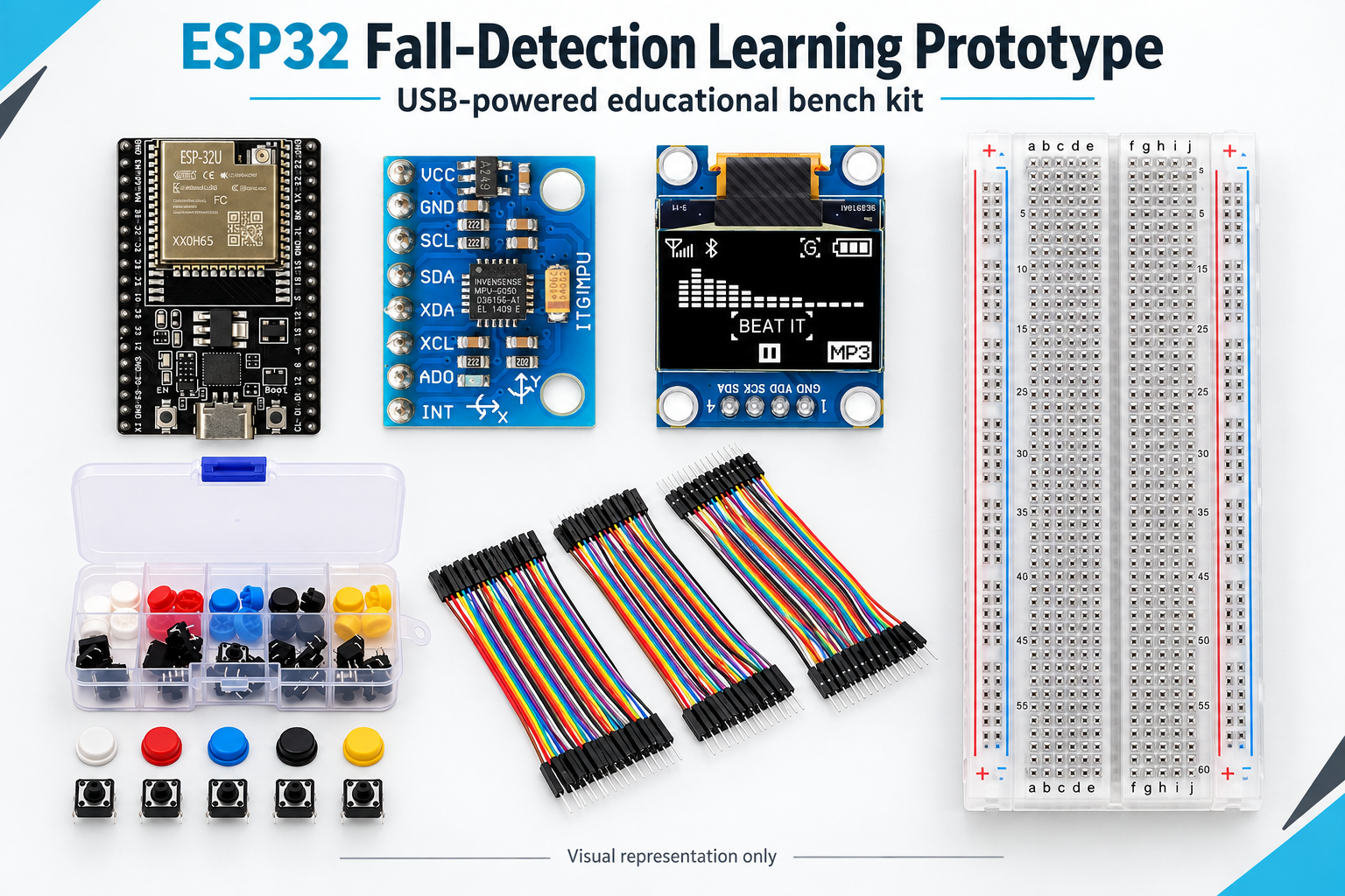
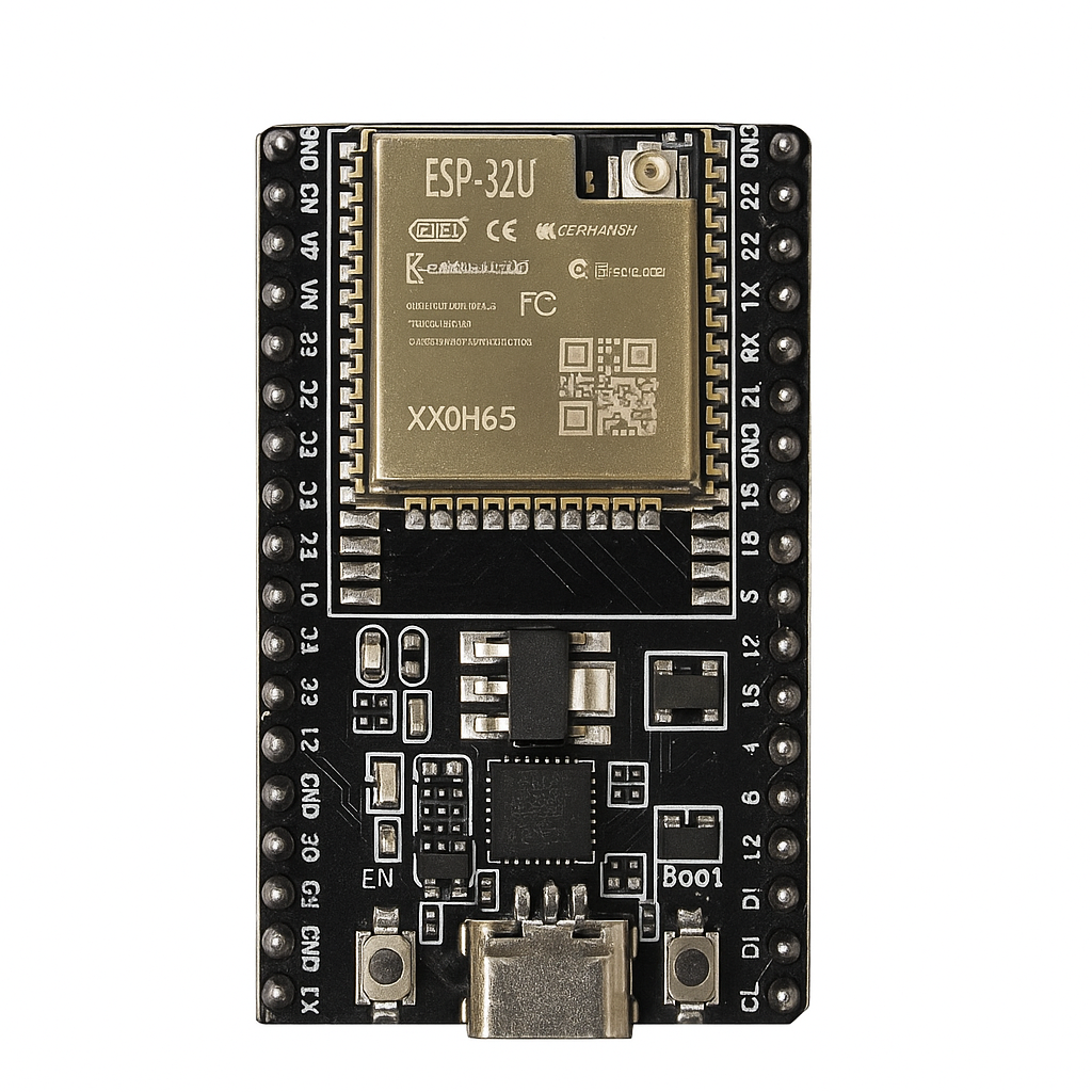
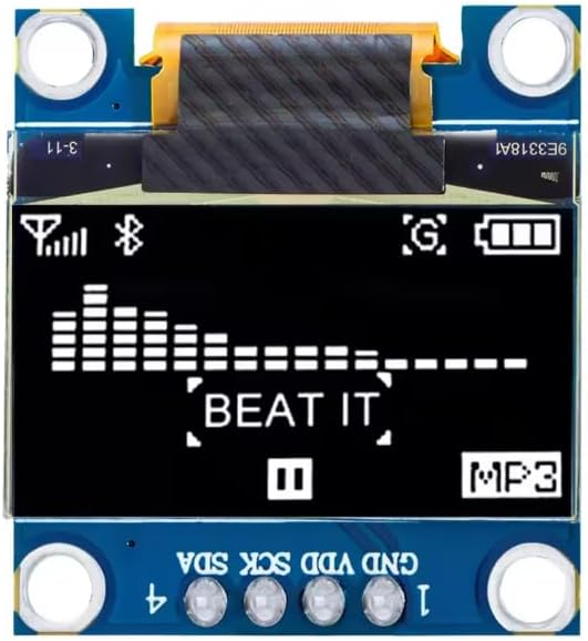
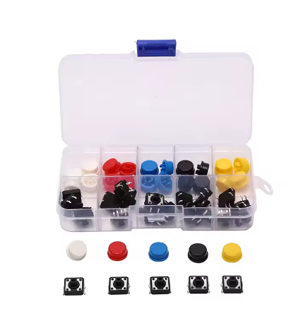
Every item below is in the kit. Not in the box: The buzzer module (optional add-on).


ESP32 Fall-Detection Learning Prototype
All 6 parts in one box, with this project and 4 more to build from them.
Need only these parts? Order them loose · from AED 122.13
One of each part. Packs (resistor assortment, jumper wires) already hold more than a single build needs. Backorder parts ship once they arrive. Delivery is AED 20, free on orders AED 100+.
Connections
Unplug USB before you change any wire. Pin names are the labels printed on the board.
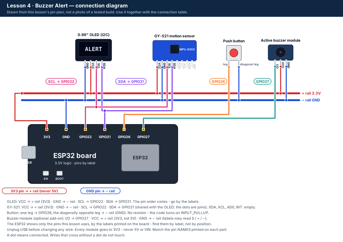
| Part / pin | Connect to | Note |
|---|---|---|
| Buzzer I/O (signal) | GPIO27 | May be labelled S or IN |
| Buzzer VCC | + rail (3V3) | Not 5V - see "How it works" |
| Buzzer GND | − rail (GND) | |
| OLED, GY-521, button | As in Lessons 1-3 | GPIO21, GPIO22, GPIO26 |
Step by step
One thing at a time. Tick nothing off until it matches the diagram.
- Unplug the USB cable.Watch out: Always unplug the USB cable before you add, move or remove a wire.
- Read the buzzer module's 3 labels: I/O (or S or IN), VCC and GND.Watch out: Go by the labels, not the position.
- Wire I/O to GPIO27, VCC to the + rail (3V3) and GND to the − rail, using female-to-male jumpers.Watch out: VCC goes to 3V3, not 5V.
- Plug in USB and upload the Lesson 4 code. Listen for 3 short test beeps.Watch out: Keep the buzzer away from your ears.
- Press the button: ALERT, beeping. Press again: stopped. Start one more and wait 15 seconds without pressing.
Sketch for this project
Written for the board in the kit. Copy it into the Arduino IDE; change the pin numbers if you wire it differently.
/*
  DIY KIT - ESP32 Fall-Detection Learning Prototype
  Lesson 4 of 5: Buzzer Alert

  WIRING (unplug the USB cable before you wire)
    Keep everything from Lessons 1-3.
    Active buzzer module, with 3 female-to-male jumper wires:
      I/O (signal, may be labelled S or IN) -> GPIO27
      VCC                                   -> 3V3  (NOT 5V - see the lesson)
      GND                                   -> GND

  WHAT SHOULD HAPPEN
    Three short test beeps. Then press the button to start an ALERT: the
    buzzer beeps 150 ms on, 350 ms off and the OLED says ALERT. Press again
    to acknowledge (stop) it. If nobody presses, it stops by itself after
    15 seconds. Serial Monitor at 115200 baud.
*/

#include <Wire.h>
#include <Adafruit_GFX.h>
#include <Adafruit_SSD1306.h>

const int SDA_PIN = 21;
const int SCL_PIN = 22;
const int BUTTON_PIN = 26;
const int BUZZER_PIN = 27;
const unsigned long BEEP_ON_MS = 150;
const unsigned long BEEP_OFF_MS = 350;
const unsigned long MAX_ALERT_MS = 15000;   // an alarm must not run for ever
const unsigned long DEBOUNCE_MS = 35;

// Most modules beep when the pin is HIGH. If yours beeps in the gaps or
// all the time, change false to true and upload again.
const bool BUZZER_ACTIVE_LOW = false;

Adafruit_SSD1306 display(128, 64, &Wire, -1);
bool displayOk = false;
bool alerting = false;
unsigned long alertStart = 0;
bool rawButton = HIGH, stableButton = HIGH;
unsigned long rawSince = 0;

void buzzer(bool on) {
  if (BUZZER_ACTIVE_LOW) digitalWrite(BUZZER_PIN, on ? LOW : HIGH);
  else                   digitalWrite(BUZZER_PIN, on ? HIGH : LOW);
}

bool pressedNow() {
  bool reading = digitalRead(BUTTON_PIN);
  if (reading != rawButton) {
    rawButton = reading;
    rawSince = millis();
  }
  if (millis() - rawSince > DEBOUNCE_MS && reading != stableButton) {
    stableButton = reading;
    return stableButton == LOW;
  }
  return false;
}

void show(const char *line1, const char *line2) {
  if (!displayOk) return;
  display.clearDisplay();
  display.setTextColor(SSD1306_WHITE);
  display.setTextSize(1);
  display.setCursor(0, 0);
  display.println("BUZZER ALERT LAB");
  display.setTextSize(2);
  display.setCursor(0, 20);
  display.println(line1);
  display.setTextSize(1);
  display.setCursor(0, 56);
  display.println(line2);
  display.display();
}

void setup() {
  Serial.begin(115200);
  pinMode(BUTTON_PIN, INPUT_PULLUP);
  pinMode(BUZZER_PIN, OUTPUT);
  buzzer(false);
  Wire.begin(SDA_PIN, SCL_PIN);
  displayOk = display.begin(SSD1306_SWITCHCAPVCC, 0x3C) || display.begin(SSD1306_SWITCHCAPVCC, 0x3D);

  Serial.println("Lesson 4: three test beeps");
  for (int i = 0; i < 3; i++) {
    buzzer(true);  delay(100);
    buzzer(false); delay(200);
  }
  show("READY", "press to start alert");
  Serial.println("Press the button to start an alert, press again to stop it");
}

void loop() {
  bool pressed = pressedNow();
  unsigned long now = millis();

  if (!alerting) {
    if (pressed) {
      alerting = true;
      alertStart = now;
      Serial.println("ALERT started");
      show("ALERT", "press to acknowledge");
    }
  } else {
    unsigned long used = now - alertStart;
    if (pressed || used >= MAX_ALERT_MS) {
      alerting = false;
      buzzer(false);
      Serial.println(pressed ? "ACKNOWLEDGED" : "TIMED OUT after 15 s");
      show(pressed ? "STOPPED" : "TIMED OUT", "press to start alert");
    } else {
      // Where are we in one 500 ms beep cycle? The first 150 ms are "on".
      unsigned long phase = used % (BEEP_ON_MS + BEEP_OFF_MS);
      buzzer(phase < BEEP_ON_MS);
    }
  }
  delay(2);
}Upload it
- Click Copy (or Download .ino and open the file).
- In the Arduino IDE choose File → New Sketch, select everything in it and paste.
- Check the bottom of the window says Arduino Uno and your port (Start here, step 5).
- Click Upload (the → arrow) and wait for Done uploading.
How the code works
| In the code | What it does |
|---|---|
| const int BUZZER_PIN = 27; | The buzzer's signal pin. |
| const bool BUZZER_ACTIVE_LOW = false; | Most modules beep when the pin is HIGH. If yours beeps in the gaps or all the time, change it to true. |
| used % (BEEP_ON_MS + BEEP_OFF_MS) | Where we are in each 500 ms cycle; under 150 means "beep". |
| MAX_ALERT_MS = 15000 | The time-out: the alert stops by itself after 15 seconds. |
Change it and see
What you should see or hear
- Three short beeps at start, then "READY" on the OLED.
- Press: "ALERT" and 2 beeps a second. Press again: "STOPPED" and silence.
- Without a press, "TIMED OUT" after 15 seconds.
If it doesn't work
| Problem | What to check |
|---|---|
| No sound at all | Unplug USB. Check I/O to GPIO27, VCC to 3V3 and GND, by the labels. Some 5 V modules are very quiet or silent at 3.3 V - tell us if yours is. |
| It beeps in the gaps, or all the time | Your module beeps when the pin is LOW. Set BUZZER_ACTIVE_LOW to true and upload again. |
| Only a click, no beep | It may be a passive buzzer. Check the label says active, or ask us. |
| "OLED not found" or a black screen | Unplug USB. Check OLED VCC to 3V3 (not 5V), GND, SDA to GPIO21 and SCL to GPIO22 - by the labels printed on the OLED. |
| The upload fails or stops at "Connecting..." | See Start here, step 6. |
Small experiment
Time how long the alert runs before TIMED OUT with a stopwatch. Then change MAX_ALERT_MS and check again.
Check what you learned
Why is the buzzer powered from 3V3 and not 5V?
So the ESP32's 3.3 V signal can switch it fully off; at 5V it might never stop.
What is 1300 % 500?
300.
Why does the alert have a time-out?
An alarm that can never stop is a problem too - and the battery or the people nearby would suffer.
Next
- Lesson 5 puts it all together: the motion rule, the countdown, the button and the buzzer.
Stuck?
Most problems are one wire in the wrong hole. Check these first:
- Unplug, then compare every wire with the lesson's diagram and table. One pin off is the most common problem.
- Are all VCC wires on 3V3 (not 5V or VIN), and all GND wires on GND?
- OLED and GY-521: SDA on GPIO21 and SCL on GPIO22, by the labels on each module?
- Serial Monitor: is it set to 115200 baud?
- Upload problems: Tools → Board = ESP32 Dev Module, the right port, and hold BOOT if it stops at "Connecting". (Start here, step 6.)
Open the troubleshooting table for this step →
Hi DIY KIT, I'm stuck on the ESP32 Fall-Detection Learning Prototype.
Lesson: __
Step number: __
What should happen: __
What happens instead: __
Error message (copied exactly): __
I'll attach a photo of my wiring.
More from this kit
Lesson 1: Button & OLED Countdown
A button starts a 20-second countdown on the OLED and a second press cancels it - the user-interface half of the fall detector, with no motion yet. Do Start here first.
Lesson 2: Tilt Angle from a Baseline
The GY-521 learns which way is "upright" in 3 seconds, then the OLED shows how far you have tilted it from there - and flags 55°, the limit the main build uses.
Lesson 3: Motion Data Lab
Watch total g-force on a live graph and count every impact (above 2.5 g) and free fall (below 0.45 g). Choose the main build's limits from your own data.
