Overview
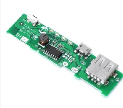
This 5V power bank PCB module is a compact all-in-one solution for building a DIY portable USB power source using a single 18650 Li‑ion cell (1S). The board integrates two critical functions: a battery charging section that accepts 5V input through a Micro USB connector, and a step-up (boost) converter that raises the battery voltage (typically 3.0–4.2V depending on state of charge) to a regulated 5V output on a USB-A port. It is intended for makers who need a small, ready-to-wire power subsystem for prototypes, handheld devices, and low-power embedded electronics.
Technical Details
The module combines a Li‑ion charge controller and a switching boost regulator on one PCB. When a 5V source is connected to the Micro USB input, the charging circuit manages the battery charge profile appropriate for 1-cell lithium chemistry (exact algorithm and charge termination behavior vary by module revision—check the controller IC datasheet if identified on your board). The boost stage uses an onboard inductor and switching controller to convert the battery’s variable voltage to a stable 5V rail suitable for USB-powered loads.
The USB-A output is designed to supply 5V to external devices. While the product name references 5V 1A, real-world continuous current depends on factors such as battery internal resistance, cable quality, PCB copper, ambient temperature, and the specific IC revision used. For reliable operation, treat 1A as an upper bound and validate under your load profile. Voltage drop under high load can occur if the battery is low or the module is thermally constrained.
Battery connection is made via clearly labeled solder pads (typically B+ and B-). Correct polarity is essential; reverse connection can damage the module and battery. Many boards of this class also include basic protection features (overcharge/overdischarge/overcurrent) depending on the controller and protection IC used; because protection implementation differs across similar-looking modules, confirm by inspecting the PCB markings and IC part numbers or by testing.
Specifications
- Battery type: 1S Li‑ion / Li‑poly (single cell), commonly 18650
- Battery nominal voltage: 3.7V (typical for 1S Li‑ion); operating range depends on controller settings (varies by module revision)
- Charging input connector: Micro USB
- Charging input voltage: 5V (from USB power source)
- Charging current: varies by module revision; check datasheet/PCB markings
- Output connector: USB-A female
- Output voltage: 5V (regulated by boost converter; regulation quality varies with load and battery level)
- Output current: up to 1A referenced; practical continuous current varies by module revision, battery capability, and thermal conditions
- Conversion topology: switching boost (step-up) with onboard inductor
- Battery connection: solder pads (typically B+ / B-)
- Indicators/controls: may include LED/status pads or onboard LEDs depending on revision (verify on your PCB)
- PCB color/form factor: green PCB, compact power-bank style layout (as shown)
Applications
- DIY power bank / portable USB charger using a single 18650 cell
- 5V supply for Arduino-compatible boards, ESP modules, sensors, and small development setups (ensure current headroom)
- Portable projects: LED controllers, small fans, mini speakers, handheld testers, IoT prototypes
- Embedded 5V rail generation from a 1S battery in custom enclosures
Integration Notes
- Use a quality 18650 cell (preferably protected or from a reputable source). High-load performance depends heavily on the battery’s discharge rating and health.
- Keep battery leads short and adequately thick to reduce voltage drop and heating at higher currents.
- Confirm polarity before soldering to B+ and B-. Add strain relief for wires to avoid pad lift.
- If powering sensitive electronics, test output ripple/noise under load; switching converters can introduce ripple that may affect analog circuits.
- Do not exceed thermal limits: if the board becomes hot under load, reduce current draw or improve airflow/heat spreading.
- For best results, validate charging behavior with your chosen 5V adapter and battery; charge current and termination thresholds can differ by revision.
Included Components
1x 5V Power Bank PCB Module (18650 charging + boost board)