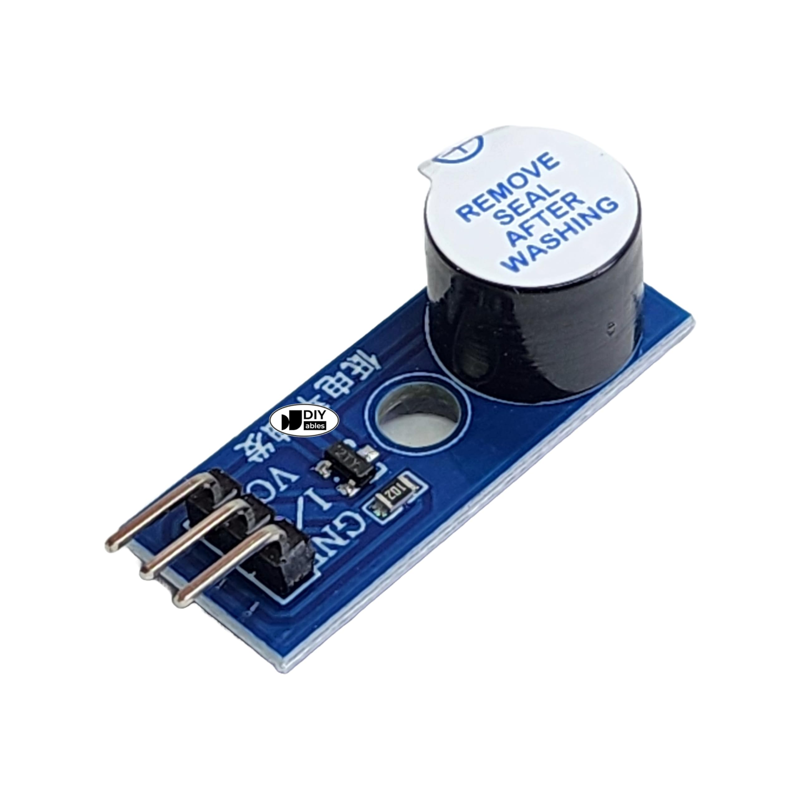
Buzzer Module for Arduino and Raspberry Pi - Active/Passive Piezo Beeper Breakout Board, 3.3V-5V Compatible, Low-Level Trigger for DIY Electronics, Robotics, and Alarm Alerts
Overview The DIY-00102 Buzzer Module is an essential, easy-to-use audio signaling component designed to simplify the process of adding acoustic feedback to your microcontroller projects.
1x Buzzer Module Breakout Board
Overview
The DIY-00102 Buzzer Module is an essential, easy-to-use audio signaling component designed to simplify the process of adding acoustic feedback to your microcontroller projects. Unlike bare piezo elements or electromagnetic buzzers that require external current-limiting resistors, flyback diodes, and switching transistors to prevent damaging sensitive microcontroller pins, this module integrates all necessary driver circuitry onto a single, compact breakout board. Featuring a standard three-pin header interface, it allows hobbyists, students, and professional engineers to achieve instant audio output within seconds of wiring. Whether you are building an audible alarm, a user interface with button-press confirmation, or a simple musical device, this module provides a reliable and clean hardware solution. Depending on the specific module revision, it may house either an active buzzer (which generates a fixed-frequency tone automatically when supplied with direct current) or a passive buzzer (which requires an external AC signal or PWM frequency to vibrate the internal diaphragm and produce varying pitches).
Technical Details
At the core of the module is a high-quality acoustic transducer paired with an onboard transistor driver circuit (typically utilizing an S8050 or equivalent NPN/PNP transistor). Microcontroller I/O pins are generally limited to outputting 20mA to 40mA of current, which is often insufficient or highly stressful for driving inductive buzzer coils directly. The integrated transistor on this breakout board acts as a digital switch: a low-current control signal from your Arduino, ESP32, or Raspberry Pi triggers the transistor, which then switches the higher current required by the buzzer directly from the VCC power rail. This design protects your microcontroller from current overdraw and inductive voltage spikes. The module is engineered to operate seamlessly across a wide voltage range, accommodating both legacy 5V systems like the Arduino Uno and modern 3.3V platforms like the ESP8266, ESP32, Raspberry Pi, and micro:bit.
Specifications
- Operating Voltage: 3.3V to 5V DC (varies by module revision)
- Operating Current: Less than 30mA (typical when active)
- Driver Transistor: Onboard S8050 or equivalent switching transistor
- Interface Type: 3-pin header (VCC, GND, I/O Signal)
- Control Logic: High or Low level trigger (check datasheet or module marking for specific revision behavior)
- Sound Output Level: 85dB minimum at 10cm (typical, varies by acoustic element)
- Resonant Frequency: 2300Hz +/- 300Hz (typical for active variants)
- Frequency Range: 100Hz to 10kHz (for passive variants using PWM/tone generation)
- Dimensions: Approximately 25mm x 15mm x 12mm (excluding header pins; check datasheet for exact mechanical tolerances)
- Mounting Hole: 3mm diameter for secure mechanical fastening
Applications
- Audible User Feedback: Generate distinct click tones or confirmation beeps when buttons are pressed on control panels.
- Security and Alarm Systems: Produce loud, continuous, or pulsing alert sirens for intrusion detection, fire alarms, or environmental sensor thresholds.
- System Diagnostics: Implement error codes using sequences of long and short beeps to diagnose headless systems without displays.
- Robotics and Toys: Add personality to mobile robots with simple melodies, warning beeps when reversing, or collision alerts.
- Educational Kits: Serve as a fundamental teaching tool in STEM classrooms to demonstrate digital outputs, PWM frequency generation, and basic circuit design.
Integration Notes
To integrate the module, connect the VCC pin to a 3.3V or 5V power source on your microcontroller board, connect GND to the common system ground, and connect the I/O or Signal pin to any digital output pin. If your module features an active buzzer, driving the signal pin to its active state (typically HIGH) will immediately sound the buzzer at its pre-set resonant frequency. If your module is a passive variant, you must apply a square wave signal to the input pin. For Arduino users, this is easily achieved using the native tone(pin, frequency, duration) function, which allows you to generate custom musical scales, multi-tone sirens, and complex audio patterns. Always verify the specific trigger logic (high-level vs. low-level trigger) of your module revision before deploying code to prevent continuous, unintended beeping.
Included Components
1x Buzzer Module Breakout Board
No reviews for this component yet.
Related Components

 In Stock