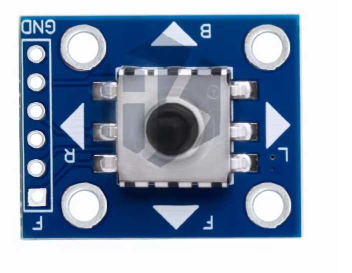
5-Way Navigation Button Module for Arduino, Raspberry Pi & ESP32 Projects, 5-Direction Tact Switch Keypad Board with Center Press, Digital Input Control for Menus, Robotics & DIY UI
Overview The 5-Way Navigation Button Module is a compact input board designed to provide a familiar “D-pad” style control for embedded projects. It combines five tactile switch actions—Up, Down, Left, Right, and a Center/OK press—into a single module that can be wired to a microcontroller or single-board computer for reliable menu…
1x 5-Way Navigation Button Module
Overview
The 5-Way Navigation Button Module is a compact input board designed to provide a familiar “D-pad” style control for embedded projects. It combines five tactile switch actions—Up, Down, Left, Right, and a Center/OK press—into a single module that can be wired to a microcontroller or single-board computer for reliable menu navigation and user input. This style of control is widely used in DIY user interfaces because it is intuitive, fast to operate, and easy to map to on-screen menus, robotics functions, or parameter adjustments.
Technical Details
This module is typically implemented as five momentary tactile switches arranged mechanically around a central switch. Electrically, each direction is presented as an independent button signal intended to be read by GPIO. Most module revisions are designed for straightforward digital input: you connect each button line to a GPIO and use pull-up or pull-down resistors (either external or internal pull resistors available on many MCUs). When a direction is pressed, the corresponding line changes logic state (exact active level and resistor arrangement can vary by module revision—verify with the board silkscreen and/or datasheet).
Because tactile switches are mechanical, contact bounce is expected. For stable readings, implement debouncing in firmware. Common approaches include:
- Time-based debounce (e.g., ignore changes for a short interval after a detected edge)
- State-machine debounce (require stable state for N consecutive samples)
- Interrupt + software debounce (trigger on edge, then confirm after delay)
If your project is noise-sensitive or uses long wires, consider enabling internal pull-ups, keeping signal wires short, and adding optional RC filtering (values depend on your sampling rate and required responsiveness). For Raspberry Pi, ensure GPIO is configured correctly and avoid applying voltages outside the Pi’s GPIO tolerance; use the Pi’s internal pulls and read the inputs at 3.3 V logic levels.
Specifications
- Input type: 5 independent momentary button outputs (Up/Down/Left/Right/Center)
- Logic behavior: varies by module revision (commonly active-low with pull-up, but confirm on your board)
- Recommended interface: GPIO digital inputs with pull-up/pull-down as required
- Debounce: required in software (mechanical switch bounce is normal)
- Platform compatibility: Arduino, ESP32, Raspberry Pi, and other MCU/SBC GPIO systems (verify logic level requirements per platform)
- Mechanical format: compact navigation keypad module; exact dimensions and pin count vary by module revision—check listing photos/datasheet for your SKU DIY-196
Applications
- LCD/OLED menu navigation for Arduino and ESP32 projects
- Robotics control inputs (direction selection, mode switching, speed/parameter tuning)
- Handheld DIY controllers, test jigs, and operator panels
- Game input for simple embedded games and demos
- UI navigation for sensor dashboards and data loggers
- Encoder alternative where discrete directional inputs are preferred
Integration Notes
1) Wiring: Connect each direction pin (U/D/L/R/C) to a dedicated GPIO. Connect the module’s ground reference to your controller ground. If the module provides VCC, follow the board markings; some revisions use VCC only for onboard pull-up networks (others may not require it).
2) Pull resistors: Use internal pull-ups/pull-downs if available; otherwise add external resistors. Confirm whether the switch shorts to GND or VCC when pressed.
3) Firmware: Map each input to a function (menu up/down, left/right, select). Add debounce and optionally long-press detection for richer UI control.
4) Safety/compatibility: For Raspberry Pi and other 3.3 V systems, ensure no 5 V is driven into GPIO. If your module uses VCC at 5 V for pull-ups, set VCC to 3.3 V or redesign the pull-up network accordingly (varies by module revision).
Included Components
1x 5-Way Navigation Button Module
No reviews for this component yet.
Related Components
 In Stock