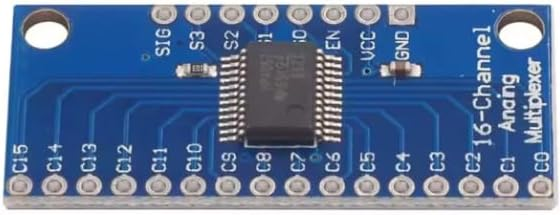
CD74HC4067 16-Channel Analog/Digital Multiplexer Module 3.3V/5V, 16:1 Signal Selector Breakout Board with S0-S3 EN SIG, for Arduino ESP32 ESP8266 ADC GPIO Sensor Expansion
Overview This CD74HC4067 16-channel multiplexer module is a practical way to expand microcontroller I/O and ADC capability without adding multiple ADC chips or large numbers of GPIO pins. The board routes one common signal pin (SIG) to any one of sixteen channel pins (C0–C15) under control of four digital address inputs (S0, S1, S2, S3).
1x CD74HC4067 16-Channel Multiplexer Module
Overview
This CD74HC4067 16-channel multiplexer module is a practical way to expand microcontroller I/O and ADC capability without adding multiple ADC chips or large numbers of GPIO pins. The board routes one common signal pin (SIG) to any one of sixteen channel pins (C0–C15) under control of four digital address inputs (S0, S1, S2, S3). An enable pin (EN) provides an additional control layer to connect or disconnect the switch network, which is useful for reducing interaction between sources, sequencing measurements, or placing the bus into a known state.
The CD74HC4067 is a CMOS analog switch device, meaning it can pass both analog voltages and digital logic levels (within the device’s supply and absolute maximum ratings). This makes it ideal for sensor expansion where multiple analog outputs must be read by a single ADC input, or where multiple digital signals must be selectively routed to a single input/output line.
Technical Details
Channel selection is performed by applying a binary address to S0–S3. The selected channel Cx is internally connected to SIG through the analog switch network. Because the switch is bidirectional, signals can flow from Cx to SIG or from SIG to Cx, enabling both multiplexing and demultiplexing use cases. EN controls whether the switch network is active; the exact active-high/active-low behavior depends on the chip variant and board wiring—verify against the module silkscreen and the CD74HC4067 datasheet for your revision.
As an analog switch, performance is influenced by parameters such as on-resistance (R_ON), leakage current, capacitance, and switching time. These characteristics vary with supply voltage, temperature, and manufacturer. For accurate analog measurements, allow settling time after switching channels, and consider the source impedance of each sensor. High-impedance sensors may require a buffer (op-amp follower) to reduce measurement error and speed up settling. For digital signals, ensure the logic thresholds and rise/fall times remain compatible with your MCU input requirements.
This module is commonly used with 3.3V and 5V microcontrollers. The logic level on S0–S3 and EN must be compatible with the module’s VCC. In mixed-voltage systems, avoid driving the control pins above VCC, and ensure the signal voltage on SIG/C0–C15 stays within the allowed range relative to VCC and GND (check datasheet).
Specifications
- IC: CD74HC4067 (or compatible 74HC4067 variant; may vary by module revision)
- Channels: 16 (C0–C15) to 1 common (SIG)
- Address/control lines: 4 select pins (S0, S1, S2, S3) + EN (enable)
- Supply voltage (VCC): designed for 3.3V/5V operation (exact supported range depends on IC variant; check datasheet)
- Signal type: analog and digital (bidirectional switching; signal range limited by VCC/GND and device ratings—check datasheet)
- Interface: through-hole header pads for VCC, GND, SIG, EN, S0–S3, and C0–C15
- Board features: labeled silkscreen, mounting holes (dimensions vary by module revision)
Applications
- ADC expansion: read up to 16 analog sensors using one ADC pin (e.g., potentiometers, LDRs, analog distance sensors)
- Digital input selection: scan multiple switches/buttons with fewer MCU pins
- Signal routing: select one of many sources to feed a single amplifier/ADC stage
- DIY test setups: quickly switch measurement points in prototyping and lab projects
- Robotics and automation: multiplex sensor arrays to reduce wiring and pin usage
Integration Notes
- Connect VCC and GND to your system supply. Use 3.3V with ESP32/ESP8266 projects unless your design is fully 5V-tolerant.
- Connect SIG to the MCU ADC input (for analog sensing) or to a GPIO (for digital routing), then connect sensors/signals to C0–C15.
- Drive S0–S3 from four GPIO pins to select the channel; optionally use EN for global disconnect. Add a small delay after switching channels before sampling ADC to allow settling (delay depends on sensor impedance and ADC sampling characteristics).
- Keep analog wiring short and route away from noisy digital lines. If readings are unstable, add decoupling near VCC/GND and consider buffering high-impedance sources.
- Always confirm the exact EN polarity, voltage limits, and recommended operating conditions in the CD74HC4067 datasheet for your specific module revision.
Included Components
1x CD74HC4067 16-Channel Multiplexer Module
No reviews for this component yet.
Related Components
 In Stock