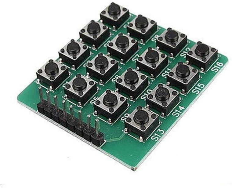
4x4 Matrix Keypad Module 16-Key Tactile Microswitch Keyboard PCB Board with 8-Pin Row/Column Header for Arduino, Raspberry Pi, ESP32 & Microcontroller Input Scanning Projects
Overview This 4x4 Matrix Keypad Module is a compact 16-key input board built with tactile microswitches on a PCB, designed for microcontroller and SBC projects that need multiple buttons without consuming excessive GPIO.
1x 4x4 16-Key Matrix Keypad Module (PCB)
Overview
This 4x4 Matrix Keypad Module is a compact 16-key input board built with tactile microswitches on a PCB, designed for microcontroller and SBC projects that need multiple buttons without consuming excessive GPIO. Instead of dedicating one pin per key, the keypad uses a row/column matrix: pressing a key connects one row line to one column line. Your firmware scans the matrix to determine which key is pressed, making it a practical choice for Arduino-compatible boards, Raspberry Pi (via GPIO), ESP32, and other development platforms.
Technical Details
The keypad is wired as a 4-row by 4-column switch matrix. Each button is a momentary, normally-open tactile switch. When pressed, it electrically bridges a specific row and column trace. The module breaks out the matrix to an 8-pin header (4 row lines + 4 column lines). In typical scanning, the MCU sets one group (rows or columns) as outputs and the other group as inputs with pull-up or pull-down resistors enabled. The firmware then drives one output line active at a time and reads the input lines to detect closures. This approach reduces pin usage and keeps wiring clean.
Because mechanical switches can bounce, software debouncing is recommended (for example, 10–30 ms debounce time, varying by application). For multi-key detection, matrix keypads may exhibit “ghosting” when multiple keys are pressed simultaneously unless isolation diodes are used. This module is commonly used for single-key-at-a-time interfaces (menus, numeric entry, function selection). If your project requires reliable multi-key rollover, consider adding external diodes per key or limiting accepted combinations in firmware.
The board is suitable for 3.3V and 5V logic environments because it is a passive switch matrix (no active IC). Actual electrical behavior depends on how you configure GPIO direction and pull resistors. For Raspberry Pi and other 3.3V-only GPIO devices, ensure no external 5V is applied to input pins.
Specifications
- Key count: 16 keys
- Matrix size: 4 rows x 4 columns
- Switch type: momentary tactile microswitch, normally open
- Electrical interface: passive switch matrix (no onboard controller)
- Output pins: 8 total (4 row + 4 column)
- Logic level compatibility: depends on host GPIO configuration; commonly used with 3.3V and 5V systems
- Debounce: required in software (timing varies by firmware and switch behavior)
- Ghosting protection: not guaranteed (varies by module revision; typically no per-key diodes)
- PCB labeling: switch positions marked (S1–S16) as shown
- Dimensions, header pitch, and exact pin order: varies by module revision; verify against the board silkscreen and your wiring before powering
Applications
- PIN/password entry pads for DIY locks, safes, and access control prototypes
- Menu navigation and parameter input for instruments, power supplies, and controllers
- Robotics and RC control panels (mode select, start/stop, function keys)
- Test fixtures and production jigs requiring multiple discrete inputs
- Educational projects demonstrating matrix scanning, interrupts, and debouncing
Integration Notes
1) Wiring: Connect the 8-pin header to GPIO. Identify which pins are rows vs columns by the PCB traces/silkscreen (varies by revision).
2) GPIO setup: Configure rows as outputs and columns as inputs with internal pull-ups (or the reverse). Scan one output line at a time.
3) Debounce: Implement software debounce to avoid repeated triggers.
4) Multiple key presses: If your UI expects only one key press at a time, enforce it in code to avoid ghosting ambiguity.
5) Raspberry Pi: Use 3.3V GPIO only; do not inject 5V into GPIO. Use internal pulls or external resistors as needed.
Included Components
1x 4x4 16-Key Matrix Keypad Module (PCB)
No reviews for this component yet.
Related Components

 In Stock