Overview
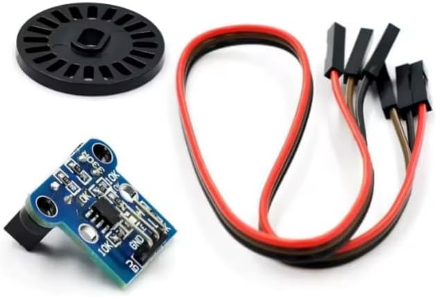
The HC-020K photoelectric speed measurement module is a compact optical encoder-style sensor designed to convert rotational motion into clean digital pulse signals. It uses a slotted encoder disc (included, 25.6mm diameter) passing through an optical interrupter to generate pulses as the disc rotates. By counting pulses over time (frequency measurement) or measuring time between pulses (period measurement), your controller can calculate RPM, angular velocity, or relative speed. This module is commonly used in DIY robotics, motor speed monitoring, and feedback systems where contactless sensing reduces mechanical wear and improves repeatability.
Technical Details
This module operates on the photo-interruption principle: an IR emitter and receiver face each other across a gap. When the encoder disc’s slots pass through the gap, the light path alternates between blocked and unblocked, producing a pulse train. The onboard circuitry conditions the sensor signal into a logic-level output on the OUT pin. Many HC-020K boards are marketed as “double speed measurement,” typically indicating two pulse outputs per mechanical slot cycle or a higher effective pulse rate; the exact pulse-per-revolution relationship depends on the disc slot count and the specific board revision, so it’s best verified during calibration.
For accurate RPM measurement, connect OUT to a microcontroller interrupt-capable pin and count rising (or falling) edges over a fixed gate time (e.g., 100 ms to 1 s). For higher precision at low speeds, measure the time between edges using a hardware timer. Debouncing is generally not required because the output is optical, but electrical noise from motors can couple into wiring; use short leads, proper grounding, and optional RC filtering or software validation if needed.
Specifications
- Module type: Photoelectric speed measurement / optical interrupter encoder module
- Encoder disc diameter: 25.6mm (provided)
- Interface pins: VCC, GND, OUT (3-pin)
- Output signal: Digital pulse output (logic-level; exact voltage level depends on supply and module design)
- Supply voltage: Varies by module revision (commonly used with 3.3V–5V systems; check datasheet/board markings)
- Channels: Marketed as “double speed measurement” (effective pulse rate/output behavior varies by revision)
- Mounting: PCB mounting holes present (size/spacing varies by module revision)
- Cable/connector: Jumper wires included (type/length may vary by kit)
Applications
- DC motor RPM sensing for speed controllers and governors
- Robotics wheel speed feedback and basic odometry (with suitable mechanical mounting)
- Tachometer projects and rotational speed displays
- Conveyor/roller speed monitoring in small automation builds
- Educational labs for interrupts, timers, and frequency measurement
Integration Notes
- Mechanical alignment is critical: ensure the encoder disc runs centered in the optical gap without rubbing.
- Determine pulses-per-revolution (PPR) experimentally: rotate one full revolution and count pulses to calibrate RPM calculations.
- Use interrupt-based counting for reliable high-speed measurement; polling may miss pulses at higher RPM.
- For noisy motor environments, route sensor wiring away from motor leads, add decoupling on VCC near the module, and share a solid ground reference.
- If using 3.3V MCUs, confirm the OUT high level is compatible at your chosen VCC; when in doubt, power the module at 3.3V if supported by your revision.
Included Components
HC-020K module, 25.6mm encoder disc, jumper wires set