Sharjah, UAE GST
Home/ Kits/ ESP32 ECG & Optical Pulse Learning Kit
Kit Advanced 3-5 hours; supervised signal experiments extra 6 parts 8 projects 14-step build guide

ESP32 ECG & Optical Pulse Learning Kit

AED 101.50 All the parts, unassembled — you build it 5 kits packed and ready to ship

Buying these 6 parts one by one costs AED 152.87 — the kit saves you AED 51.37 (34%).

Education-only biomedical electronics kit

Not a medical device. Never use readings for diagnosis, treatment, emergencies, patient monitoring, fitness certification, or health decisions.

  • Begin with recorded data, I2C checks, optical experiments, and AD8232 leads-off tests with no electrode attached to a person.
  • For any instructor-approved body-connected ECG lesson, run the laptop on battery only and disconnect its charger, dock, Ethernet, wired monitor, and every other wired peripheral or test instrument. USB does not provide medical isolation.
  • Keep electrodes off the body while wiring, uploading, resetting, measuring voltages, or changing connections. Never attach an oscilloscope, bench supply, or mains-connected instrument to a body-connected circuit.
  • Use only clean, intact skin and verified compatible disposable pads. Do not use with implanted electronic devices. Stop immediately for irritation, discomfort, damaged leads, heating, or unexpected behavior.
  • Power every required module from 3.3 V and keep ESP32 inputs within 0-3.3 V. Verify the exact module labels and AD8232 output range before connection.
  • The firmware is compiler-checked, not physically bench-tested with the exact catalog assembly. It deliberately omits SpO2 and labels BPM as experimental.

Recommended age: 16+ with instructor supervision.

ESP32 ECG & Optical Pulse Learning Kit
KIT-7 · ESP32

Explore raw ECG acquisition, AD8232 leads-off detection, MAX30102 optical waveforms, experimental pulse-interval estimation, and OLED status display with ESP32. The checked firmware starts paused, requires a safety acknowledgement before ECG modes, and deliberately omits SpO2. Education only; not a medical device.

Difficulty
Advanced
Build time
3-5 hours; supervised signal experiments extra
Parts included
6 components
Build guide
14 steps

Included parts (6)

6 parts packed in this kit

Lost or damaged a part? Every part name below opens its own page, so you can buy a replacement or an extra on its own.

Substitutions
Need a part swapped?
Any component here can be substituted — a different board, a larger breadboard, extra sensors for a classroom set.
Ask for a variant

8 projects in this kit

Every one is built from the parts in the box, plus the basics listed under You'll also need.

Basics 01

I2C address and bus inventory

Run the firmware scan command with each module added separately, then together. Confirm the OLED responds at 0x3C or 0x3D and the MAX30102 at 0x57. Record any address or startup failure before attempting signal experiments.

ESP32U DIY-003 OLED MAX30102 breadboard jumper wires
Parts, guide & add to cart →
Basics 02

MAX30102 raw optical waveform

Use optical mode to stream raw red and infrared samples. Compare no-finger, lightly placed fingertip, firm pressure, ambient-light, and motion conditions. Treat every number as an uncalibrated learning signal; the firmware does not calculate SpO2.

ESP32U MAX30102 breadboard jumper wires
Parts, guide & add to cart →
Basics 03

Experimental optical pulse interval

Observe how the beat detector estimates pulse intervals only when the infrared signal exceeds a provisional quality threshold. Compare stable and moving fingers and explain why this is not a validated heart-rate monitor.

ESP32U MAX30102 optional OLED breadboard jumper wires
Parts, guide & add to cart →
Basics 04

AD8232 leads-off logic

Keep electrodes off the body and test the LO+ and LO- lines by connecting and disconnecting the supplied lead cable as permitted by its documentation. Verify that the firmware reports leads off and suppresses the ECG value instead of showing a misleading trace.

ESP32U AD8232 breadboard jumper wires
Parts, guide & add to cart →
Basics 05

Raw ECG Serial Plotter lesson

After the safety acknowledgement and instructor check, use plot-ecg mode to view raw waveform changes. The laptop must be on battery with charger, dock, wired monitor, Ethernet, and test instruments disconnected. Education only; never use the trace for health decisions.

ESP32U AD8232 breadboard jumper wires verified leads and pads battery-operated laptop
Parts, guide & add to cart →
Display 06

OLED signal-quality display

Display the active mode, optical signal status, experimental BPM estimate, and AD8232 leads-off state. The display intentionally labels the build education-only and shows no SpO2 value.

ESP32U DIY-003 OLED MAX30102 AD8232 breadboard jumper wires
Parts, guide & add to cart →
Basics 07

ECG and optical timing comparison

Capture timestamped electrical and optical events and discuss sensor, filtering, and transmission delays. This is an advanced timing lesson, not a blood-pressure or clinical measurement method.

Completed supervised build with AD8232 MAX30102 OLED ESP32U breadboard and jumpers
Parts, guide & add to cart →
Basics 08

Recorded-data filtering study

Compare raw and smoothed ECG or PPG sample files without connecting sensors to a person. Measure how filtering changes noise, peak height, and timing, and explain why aggressive smoothing can create misleading results.

Computer spreadsheet or analysis software instructor-provided non-identifying sample data
Parts, guide & add to cart →
BUILD GUIDE - ESP32 - ADVANCED SUPERVISED LAB

ESP32 ECG & Optical Pulse Learning Kit

Build a two-path biosignal learning station: explore reflected-light pulse signals with the MAX30102, then study raw ECG waveform acquisition and lead-off detection with the AD8232 under strict instructor supervision.

8 guided projects6 included items3-5 hours3.3 V systemAge 16+

What you will build

Optical signal station

Read raw red and infrared samples, compare signal quality, observe motion artefacts, and calculate an experimental pulse interval. The project deliberately does not calculate SpO2.

ECG learning station

Capture the AD8232 raw analogue output, inspect lead-off states, and view a waveform in the Serial Plotter. This path remains locked until the safety acknowledgement is entered.

Shared status display

Use the SSD1306 OLED to show the current mode, sensor state, raw values, experimental BPM, and leads-off condition.

Education only: this kit is not a medical device and its output must never be used for diagnosis, treatment, emergency decisions, patient monitoring, or fitness certification.

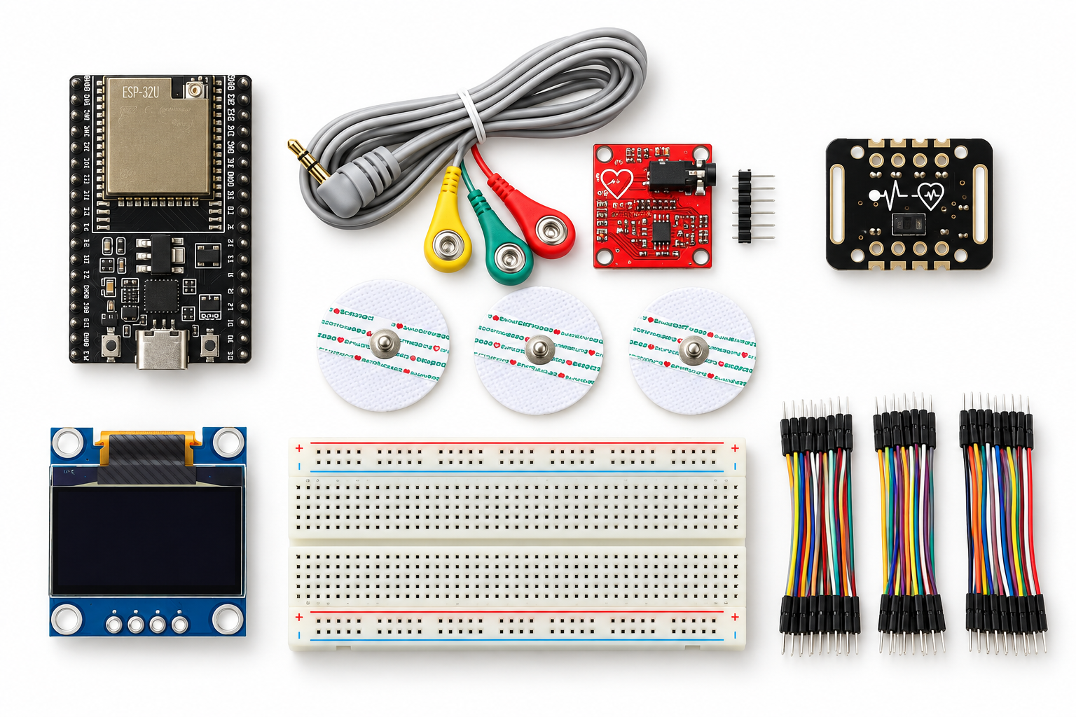
What is included

ItemQtyPurpose
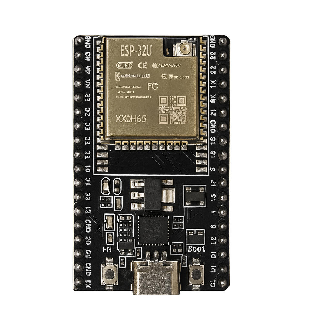
ESP32U development board1Main 3.3 V controller, USB programming, ADC and I2C.
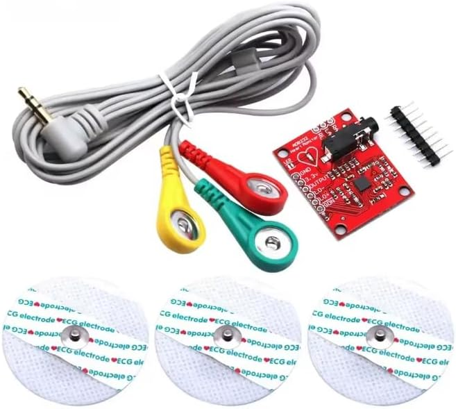
DIY-012 AD8232 ECG module pack1Educational ECG front end with raw output and LO+/LO- lead detection. Verify the exact cable, pads, labels, and headers supplied.
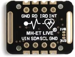
MAX30102 module1Optical red/infrared signal acquisition on I2C address 0x57.
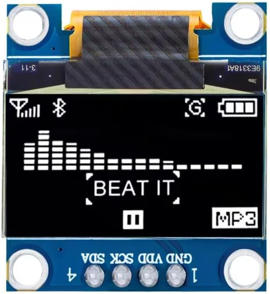
DIY-003 SSD1306 128x64 OLED13.3 V I2C status display; normally 0x3C or 0x3D and identified by the scanner.
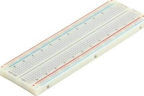
DIY-217 full-size 830 tie-point breadboard1Provides enough room for the controller, modules, rails, and signal wiring.
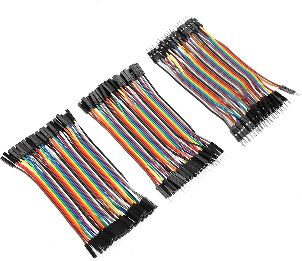
DIY-212 jumper-wire set1Signal, power, and ground connections; select the connector genders that match the installed headers.

Product photographs and diagrams are visual representations only. Check the packed items and printed module labels before wiring.

What you also need

Programming

A computer with Arduino IDE 2.x, a known-good USB-A to USB-C data cable, and permission to install the ESP32 board package and listed libraries.

Inspection

A digital multimeter, good lighting, labels or masking tape, notebook, and a phone or camera for recording the final wiring. Measure only while no electrodes are attached to a person.

Body-connected extension

Only the verified lead cable and compatible fresh disposable electrode pads supplied with or approved for the exact AD8232 pack. Use clean, intact skin and instructor supervision.

Important: the catalogue does not currently link a USB data cable to this template. Confirm one is packed or tell the customer to supply it.

Safety barrier before ECG

  1. Complete programming, I2C scanning, and all voltage checks with no electrode attached to a person.
  2. For any instructor-approved body-connected lesson, run the laptop from its internal battery only.
  3. Disconnect the charger, dock, Ethernet, wired monitor, powered USB hub, bench supply, oscilloscope, and every other mains-connected peripheral or instrument.
  4. Do not assume USB is medical isolation. Never connect a body-connected circuit to mains-powered test equipment.
  5. Keep electrodes off the body during uploads, resets, wiring changes, continuity tests, or voltage measurements.
  6. Do not use with implanted electronic devices. Stop immediately for irritation, discomfort, damaged leads, heating, or unexpected behaviour.

Reviewed pin plan

Module pinESP32 connectionCheck before power
OLED VCC / GND3V3 / GNDConfirm the module label and polarity.
OLED SDA / SCLGPIO21 / GPIO22Scanner should find 0x3C or 0x3D.
MAX30102 VIN or VCC / GND3V3 / GNDUse 3.3 V for the kit configuration; confirm breakout labels.
MAX30102 SDA / SCLGPIO21 / GPIO22Shared I2C bus; scanner must find 0x57.
AD8232 3.3V / GND3V3 / GNDDo not feed the module from 5 V in this build.
AD8232 OUTPUTGPIO34ADC1 input. Confirm output remains within 0-3.3 V before reconnection.
AD8232 LO+GPIO32Active-high lead-off input in the reviewed plan.
AD8232 LO-GPIO33Active-high lead-off input in the reviewed plan.
No wiring diagram is presented as verified. The table is a reviewed pin plan. The exact catalogue modules, labels, voltage range, lead-off behaviour, and physical arrangement still require bench validation.

Software setup

Board package

ESP32 Arduino core 3.3.11. Select the board profile that matches the supplied ESP32U development board and confirm its serial port.

Libraries

SparkFun MAX3010x Sensor Library 1.1.2, Adafruit SSD1306 2.5.17, Adafruit GFX 1.12.6, and Adafruit BusIO 1.17.4.

Serial settings

115200 baud with newline enabled. Start with only the ESP32 connected, then use scan and status after each module is added.

Firmware verification: the supplied sketch compiled and linked in both normal and diagnostic modes with the versions above. This does not prove the physical assembly, signal quality, or body-connected safety.

Controlled power-up sequence

  1. Upload the sketch to the ESP32 with every sensor disconnected. Confirm the safety banner, command list, and paused status.
  2. Lay out the full-size breadboard. Check whether its power rails are split; bridge only the sections you intend to use.
  3. With USB removed, connect 3V3 and GND. Check rail polarity, continuity, and 3.3 V before adding modules.
  4. Add the OLED, power up, and run scan. Record 0x3C or 0x3D.
  5. Power down, add MAX30102 on the same I2C bus, and scan again. Require 0x57 plus the OLED address.
  6. Run the optical lesson before adding the AD8232.
  7. Power down, wire AD8232 without the lead cable attached to a person, then verify output voltage and lead-off behaviour.
  8. Only after the release checks are complete may an instructor consider the restricted body-connected lesson.

Firmware commands and safeguards

CommandResultSafeguard
helpLists commands and limitations.Always available.
safetyRepeats the medical-use and isolation warning.Always available.
scanLists responding I2C addresses.Use after each I2C module is installed.
statusReports mode, sensor detection, acknowledgement state, and ECG pins.Use before acquisition.
opticalStreams raw red/IR and an experimental BPM estimate.Rejected if MAX30102 is not detected.
I-UNDERSTANDUnlocks ECG modes for the current power session.Does not verify wiring or create medical isolation.
ecgStreams timestamp, raw ADC, LO+, and LO-.Rejected until acknowledged; raw value becomes NA when leads are off.
plot-ecgProduces Serial Plotter channels.Rejected until acknowledged.
combinedStreams reduced-rate ECG and optical data.Requires acknowledgement and a detected optical module.
pauseStops acquisition.Returns to the safety screen.

Optical signal lesson

  1. Run optical with no finger present. Record the red/IR baseline and LOW signal label.
  2. Place one fingertip gently and keep it still. Avoid excessive pressure, which can change blood flow and signal amplitude.
  3. Compare stable placement, deliberate motion, room-light changes, and different pressure. Record how each condition changes the raw waveform.
  4. Treat the BPM value as an experimental interval estimate. It depends on signal quality and a provisional IR threshold that must be tuned to the exact module.
  5. Do not derive or advertise oxygen saturation. The sketch does not calculate SpO2 and has no calibration for it.

AD8232 leads-off and ECG lesson

  1. Leave the lead cable and pads disconnected from a person. Run status and verify GPIO34, GPIO32, and GPIO33 are reported.
  2. Confirm the AD8232 output cannot exceed the ESP32 0-3.3 V input range. Never measure while attached to a person.
  3. With leads disconnected, check that LO+ or LO- is high and the stream prints NA instead of an ECG value.
  4. Exercise the connector or approved test arrangement without body connection and document the actual lead-off polarity of the supplied module.
  5. Review the complete battery-only isolation rule. An instructor must sign off wiring and environment before entering I-UNDERSTAND.
  6. For an approved supervised lesson, keep the session brief, collect raw learning data, and discuss noise and artefacts rather than health interpretation.

Understanding the data

FieldMeaningDo not assume
red / irRaw reflected-light sample counts from the MAX30102.They are not calibrated medical values.
bpm_estimateAverage of recent detected pulse intervals when signal is adequate.It is not a validated heart-rate measurement.
signal LOW/PRESENTComparison with a provisional IR threshold.Presence does not prove correct placement or accuracy.
ECG raw12-bit ESP32 ADC sample of the AD8232 output.It is not a diagnostic ECG trace.
LO+ / LO-Digital lead-off indicators from AD8232.They do not prove safe electrode contact.
NAFirmware suppression because a lead-off input is active.It does not diagnose the reason for disconnection.

Eight learning projects

1. I2C address map

Use: ESP32U, OLED, MAX30102. Discover each device separately, then together, and explain why multiple devices can share SDA and SCL.

2. Optical baseline study

Use: ESP32U, MAX30102, OLED. Compare no-finger and stable-finger raw values without making a health claim.

3. Motion artefact experiment

Use: ESP32U, MAX30102. Record how small movements affect red/IR data and experimental beat detection.

4. Pressure and ambient-light comparison

Use: ESP32U, MAX30102. Change one condition at a time and document repeatability.

5. Lead-off logic tester

Use: ESP32U, AD8232. Confirm LO+/LO- behaviour without connecting electrodes to a person.

6. ECG serial plotter lab

Use: ESP32U, AD8232. After instructor safety approval, view raw educational waveform shape and identify motion and contact artefacts.

7. Dual-sensor status panel

Use: all electronic modules. Show mode, signal state, experimental BPM, and leads-off status on OLED.

8. Signal-quality investigation

Use: complete kit. Create a controlled test plan, collect repeated observations, and separate sensor limitations from firmware behaviour.

Troubleshooting

SymptomChecks
No serial portUse a data-capable cable, try another USB port, confirm the board profile, and hold BOOT only if the supplied board requires it.
No I2C devicesPower down; verify 3.3 V, common ground, SDA GPIO21, SCL GPIO22, and connector orientation.
OLED absentScan for 0x3C and 0x3D. Confirm the exact controller and pin labels on the catalogue module.
MAX30102 absentRequire address 0x57. Recheck VCC, GND, SDA, SCL, and any soldered headers.
Optical signal always LOWCheck sensor contact, orientation, ambient light, raw IR values, and tune the provisional threshold only after recording evidence.
BPM unstableReduce movement and pressure variation. Use raw data as the lesson result; do not present the estimate as medical.
ECG always NAKeep electrodes off the body while checking LO+/LO- wiring, module polarity, and the supplied lead connector.
ECG mode deniedReview the isolation state, obtain instructor approval, then type I-UNDERSTAND. The lock resets after power cycle.
Noisy ECGStop body-connected use first. Inspect lead contact and routing; never add a mains-powered instrument to investigate.

Physical release checklist

  • Exact ESP32U board profile and USB connector confirmed.
  • Full-size breadboard fit and split-rail layout recorded.
  • All required modules operate from 3.3 V in the final assembly.
  • OLED address recorded as 0x3C or 0x3D; MAX30102 recorded at 0x57.
  • AD8232 pack contents, module labels, lead cable, pads, and headers checked.
  • AD8232 output range measured with no person connected.
  • LO+ and LO- polarity physically verified and NA suppression observed.
  • Optical raw data, motion response, and experimental BPM repeatability documented.
  • Battery-only body-connected procedure reviewed by the responsible instructor.
  • Firmware uploaded and basic commands exercised on the exact assembled kit.
  • Guide photos show the shipped full-size breadboard and actual parts.
  • Template remains Needs Review until the checks above are signed off.

Scope and limitations

The firmware and pin allocation have been reviewed and compiler-checked. Normal and diagnostic builds link successfully with the stated software versions. The exact catalogue assembly has not been bench-tested in this review, and no body-connected configuration has been medically validated.

Expected I2C addresses, the provisional finger threshold, optical drive settings, AD8232 output range, lead-off polarity, breadboard fit, and supplied accessories must be confirmed on the physical kit. Keep the product in Needs Review until that work is documented.

All images are visual representations only. Actual component appearance, markings, connector positions, and accessories may vary; follow the labels on the supplied hardware.

Build steps (14)

Tick steps off as you go — your place is kept on this device.

0 / 14
These steps come from the build reference recorded for this kit. The firmware is in the Code section below.

Code

The sketch we ship with this kit. Copy it, or ask us for the version matched to your board.

1
481
arduino
ESP32 ECG and optical pulse learning lab (BiomedicalLearningLab.ino)
#include <Arduino.h>
#include <Wire.h>
#include <Adafruit_GFX.h>
#include <Adafruit_SSD1306.h>
#include "MAX30105.h"
#include "heartRate.h"

#ifndef BIOMED_DIAGNOSTIC
#define BIOMED_DIAGNOSTIC false
#endif

// Reviewed learning-lab pin plan for the ESP32 DevKit-style board in this kit.
constexpr uint8_t PIN_ECG_OUT = 34;
constexpr uint8_t PIN_ECG_LO_PLUS = 32;
constexpr uint8_t PIN_ECG_LO_MINUS = 33;
constexpr uint8_t PIN_I2C_SDA = 21;
constexpr uint8_t PIN_I2C_SCL = 22;

constexpr uint32_t SERIAL_BAUD = 115200;
constexpr uint32_t ECG_PERIOD_US = 4000;  // 250 samples/second.
constexpr uint32_t DISPLAY_PERIOD_MS = 200;
constexpr uint32_t STATUS_PERIOD_MS = 1000;
constexpr uint32_t FINGER_IR_MIN = 50000;  // Provisional; tune with the exact module.
constexpr uint8_t OLED_WIDTH = 128;
constexpr uint8_t OLED_HEIGHT = 64;
constexpr int8_t OLED_RESET = -1;

enum class RunMode : uint8_t {
  Paused,
  Optical,
  Ecg,
  Combined,
  PlotEcg
};

Adafruit_SSD1306 display(OLED_WIDTH, OLED_HEIGHT, &Wire, OLED_RESET);
MAX30105 opticalSensor;

RunMode runMode = RunMode::Paused;
bool safetyAcknowledged = false;
bool oledReady = false;
bool opticalReady = false;
uint8_t oledAddress = 0;

uint32_t nextEcgUs = 0;
uint32_t nextDisplayMs = 0;
uint32_t nextStatusMs = 0;
uint32_t lastBeatMs = 0;
uint32_t lastOpticalSampleMs = 0;
uint32_t latestRed = 0;
uint32_t latestIr = 0;
uint16_t latestEcg = 0;
bool latestLeadOffPlus = true;
bool latestLeadOffMinus = true;
float latestBpm = NAN;

float bpmHistory[4] = {NAN, NAN, NAN, NAN};
uint8_t bpmIndex = 0;
uint8_t bpmCount = 0;
uint8_t combinedEcgDivider = 0;
uint8_t opticalPrintDivider = 0;

String commandBuffer;

const char *modeName(RunMode mode) {
  switch (mode) {
    case RunMode::Optical: return "OPTICAL";
    case RunMode::Ecg: return "ECG";
    case RunMode::Combined: return "COMBINED";
    case RunMode::PlotEcg: return "PLOT_ECG";
    default: return "PAUSED";
  }
}

bool isEcgMode(RunMode mode) {
  return mode == RunMode::Ecg || mode == RunMode::Combined || mode == RunMode::PlotEcg;
}

bool isOpticalMode(RunMode mode) {
  return mode == RunMode::Optical || mode == RunMode::Combined;
}

bool i2cResponds(uint8_t address) {
  Wire.beginTransmission(address);
  return Wire.endTransmission() == 0;
}

void printSafety() {
  Serial.println();
  Serial.println(F("SAFETY - EDUCATION ONLY, NOT A MEDICAL DEVICE"));
  Serial.println(F("Never use this kit for diagnosis, treatment, emergencies, patient monitoring, or health decisions."));
  Serial.println(F("Before body-connected ECG use: run the laptop from battery only and disconnect its charger, dock,"));
  Serial.println(F("mains-connected peripherals, and test instruments. USB is not medical isolation."));
  Serial.println(F("Keep electrodes off the body while wiring, uploading, resetting, or changing connections."));
  Serial.println(F("Use only on clean, intact skin; stop if irritation, discomfort, or unexpected heating occurs."));
  Serial.println(F("Type I-UNDERSTAND to unlock ECG modes for this power session."));
  Serial.println();
}

void printHelp() {
  Serial.println(F("Commands:"));
  Serial.println(F("  help          - show this list"));
  Serial.println(F("  safety        - repeat the safety notice"));
  Serial.println(F("  scan          - scan the I2C bus"));
  Serial.println(F("  status        - report sensors, pins, and current mode"));
  Serial.println(F("  optical       - MAX30102 raw red/IR plus experimental pulse interval"));
  Serial.println(F("  ecg           - structured AD8232 raw samples; safety acknowledgement required"));
  Serial.println(F("  plot-ecg      - Arduino Serial Plotter output; safety acknowledgement required"));
  Serial.println(F("  combined      - reduced-rate ECG and optical stream; acknowledgement required"));
  Serial.println(F("  pause         - stop acquisition and return to the safety screen"));
  Serial.println(F("No SpO2 value is calculated. BPM is experimental and is shown only with adequate optical signal."));
}

void scanI2c() {
  uint8_t count = 0;
  Serial.println(F("I2C_SCAN_BEGIN"));
  for (uint8_t address = 1; address < 127; ++address) {
    if (i2cResponds(address)) {
      Serial.print(F("I2C_DEVICE,0x"));
      if (address < 16) Serial.print('0');
      Serial.println(address, HEX);
      ++count;
    }
  }
  Serial.print(F("I2C_SCAN_END,count="));
  Serial.println(count);
}

void showLines(const __FlashStringHelper *line1,
               const __FlashStringHelper *line2,
               const __FlashStringHelper *line3 = nullptr,
               const __FlashStringHelper *line4 = nullptr) {
  if (!oledReady) return;
  display.clearDisplay();
  display.setTextColor(SSD1306_WHITE);
  display.setTextSize(1);
  display.setCursor(0, 0);
  display.println(line1);
  display.println(line2);
  if (line3 != nullptr) display.println(line3);
  if (line4 != nullptr) display.println(line4);
  display.display();
}

void initDisplay() {
  if (BIOMED_DIAGNOSTIC) {
    oledReady = false;
    return;
  }

  if (i2cResponds(0x3C)) oledAddress = 0x3C;
  else if (i2cResponds(0x3D)) oledAddress = 0x3D;
  else return;

  oledReady = display.begin(SSD1306_SWITCHCAPVCC, oledAddress);
  if (oledReady) {
    showLines(F("Biomedical Lab"), F("EDUCATION ONLY"), F("Type help in Serial"));
  }
}

void initOpticalSensor() {
  if (BIOMED_DIAGNOSTIC) {
    opticalReady = true;
    return;
  }

  opticalReady = opticalSensor.begin(Wire, I2C_SPEED_FAST);
  if (!opticalReady) return;

  // Red + IR at 100 samples/s. Values are for learning and must be tuned on the exact breakout.
  opticalSensor.setup(0x1F, 4, 2, 100, 411, 4096);
  opticalSensor.setPulseAmplitudeGreen(0);
  opticalSensor.clearFIFO();
}

void printStatus() {
  Serial.print(F("STATUS,mode="));
  Serial.print(modeName(runMode));
  Serial.print(F(",diagnostic="));
  Serial.print(BIOMED_DIAGNOSTIC ? 1 : 0);
  Serial.print(F(",safety_ack="));
  Serial.print(safetyAcknowledged ? 1 : 0);
  Serial.print(F(",oled="));
  Serial.print(oledReady ? 1 : 0);
  Serial.print(F(",oled_addr="));
  if (oledAddress == 0) Serial.print(F("NA"));
  else {
    Serial.print(F("0x"));
    Serial.print(oledAddress, HEX);
  }
  Serial.print(F(",max30102="));
  Serial.print(opticalReady ? 1 : 0);
  Serial.print(F(",ecg_pin="));
  Serial.print(PIN_ECG_OUT);
  Serial.print(F(",lo_plus_pin="));
  Serial.print(PIN_ECG_LO_PLUS);
  Serial.print(F(",lo_minus_pin="));
  Serial.println(PIN_ECG_LO_MINUS);
}

void resetBpm() {
  latestBpm = NAN;
  bpmIndex = 0;
  bpmCount = 0;
  lastBeatMs = 0;
  for (float &entry : bpmHistory) entry = NAN;
}

void setMode(RunMode requested) {
  if (isEcgMode(requested) && !safetyAcknowledged) {
    Serial.println(F("DENIED: Read the safety notice and type I-UNDERSTAND first."));
    return;
  }
  if (isOpticalMode(requested) && !opticalReady) {
    Serial.println(F("DENIED: MAX30102 was not detected at I2C address 0x57."));
    return;
  }

  runMode = requested;
  nextEcgUs = micros();
  nextDisplayMs = millis();
  combinedEcgDivider = 0;
  opticalPrintDivider = 0;
  if (!isOpticalMode(runMode)) resetBpm();

  Serial.print(F("MODE,"));
  Serial.println(modeName(runMode));
  if (runMode == RunMode::Optical) {
    Serial.println(F("PPG_HEADER,t_ms,red,ir,bpm_estimate,signal"));
  } else if (runMode == RunMode::Ecg) {
    Serial.println(F("ECG_HEADER,t_us,raw,lead_off_plus,lead_off_minus"));
  } else if (runMode == RunMode::Combined) {
    Serial.println(F("COMBINED: ECG is reduced to 50 Hz and PPG to about 25 Hz for serial bandwidth."));
  } else if (runMode == RunMode::PlotEcg) {
    Serial.println(F("Serial Plotter channels: ECG_RAW and LEADS_OFF. Disconnect all mains-connected equipment."));
  }
}

void handleCommand(String command) {
  command.trim();
  command.toLowerCase();
  if (command.length() == 0) return;

  if (command == "i-understand") {
    safetyAcknowledged = true;
    Serial.println(F("SAFETY_ACKNOWLEDGED for this power session. This does not verify the wiring or make the kit medical equipment."));
  } else if (command == "help") {
    printHelp();
  } else if (command == "safety") {
    printSafety();
  } else if (command == "scan") {
    scanI2c();
  } else if (command == "status") {
    printStatus();
  } else if (command == "optical") {
    setMode(RunMode::Optical);
  } else if (command == "ecg") {
    setMode(RunMode::Ecg);
  } else if (command == "combined") {
    setMode(RunMode::Combined);
  } else if (command == "plot-ecg") {
    setMode(RunMode::PlotEcg);
  } else if (command == "pause") {
    setMode(RunMode::Paused);
  } else {
    Serial.print(F("UNKNOWN_COMMAND,"));
    Serial.println(command);
    printHelp();
  }
}

void serviceSerial() {
  while (Serial.available() > 0) {
    const char incoming = static_cast<char>(Serial.read());
    if (incoming == '\n' || incoming == '\r') {
      if (commandBuffer.length() > 0) {
        handleCommand(commandBuffer);
        commandBuffer = "";
      }
    } else if (commandBuffer.length() < 48) {
      commandBuffer += incoming;
    }
  }
}

void readLeadState() {
  if (BIOMED_DIAGNOSTIC) {
    latestLeadOffPlus = false;
    latestLeadOffMinus = false;
    return;
  }
  latestLeadOffPlus = digitalRead(PIN_ECG_LO_PLUS) == HIGH;
  latestLeadOffMinus = digitalRead(PIN_ECG_LO_MINUS) == HIGH;
}

uint16_t diagnosticEcgSample() {
  const uint16_t phase = (millis() / 4) % 250;
  if (phase < 8) return 2100 + phase * 180;
  if (phase < 18) return 3540 - (phase - 8) * 260;
  if (phase < 28) return 940 + (phase - 18) * 120;
  return 2048 + ((phase % 20) - 10) * 3;
}

void serviceEcg() {
  if (!isEcgMode(runMode)) return;

  const uint32_t nowUs = micros();
  if (static_cast<int32_t>(nowUs - nextEcgUs) < 0) return;
  nextEcgUs += ECG_PERIOD_US;
  if (static_cast<int32_t>(nowUs - nextEcgUs) > static_cast<int32_t>(ECG_PERIOD_US * 4)) {
    nextEcgUs = nowUs + ECG_PERIOD_US;
  }

  readLeadState();
  const bool leadsOff = latestLeadOffPlus || latestLeadOffMinus;
  latestEcg = BIOMED_DIAGNOSTIC ? diagnosticEcgSample() : analogRead(PIN_ECG_OUT);

  if (runMode == RunMode::PlotEcg) {
    Serial.print(F("ECG_RAW:"));
    Serial.print(leadsOff ? 0 : latestEcg);
    Serial.print(F(",LEADS_OFF:"));
    Serial.println(leadsOff ? 4095 : 0);
    return;
  }

  if (runMode == RunMode::Combined && ++combinedEcgDivider < 5) return;
  combinedEcgDivider = 0;

  Serial.print(F("ECG,"));
  Serial.print(nowUs);
  Serial.print(',');
  if (leadsOff) Serial.print(F("NA"));
  else Serial.print(latestEcg);
  Serial.print(',');
  Serial.print(latestLeadOffPlus ? 1 : 0);
  Serial.print(',');
  Serial.println(latestLeadOffMinus ? 1 : 0);
}

void addBpm(float bpm) {
  bpmHistory[bpmIndex] = bpm;
  bpmIndex = (bpmIndex + 1) % 4;
  if (bpmCount < 4) ++bpmCount;

  float sum = 0.0f;
  for (uint8_t i = 0; i < bpmCount; ++i) sum += bpmHistory[i];
  latestBpm = sum / bpmCount;
}

void processOpticalSample(uint32_t red, uint32_t ir, uint32_t nowMs) {
  latestRed = red;
  latestIr = ir;
  lastOpticalSampleMs = nowMs;

  const bool signalPresent = ir >= FINGER_IR_MIN;
  if (!signalPresent) {
    resetBpm();
  } else if (checkForBeat(static_cast<int32_t>(ir))) {
    if (lastBeatMs != 0) {
      const uint32_t interval = nowMs - lastBeatMs;
      if (interval > 0) {
        const float bpm = 60000.0f / interval;
        if (bpm >= 30.0f && bpm <= 220.0f) addBpm(bpm);
      }
    }
    lastBeatMs = nowMs;
  }

  if (++opticalPrintDivider < 4) return;
  opticalPrintDivider = 0;
  Serial.print(F("PPG,"));
  Serial.print(nowMs);
  Serial.print(',');
  Serial.print(red);
  Serial.print(',');
  Serial.print(ir);
  Serial.print(',');
  if (isnan(latestBpm)) Serial.print(F("NA"));
  else Serial.print(latestBpm, 1);
  Serial.print(',');
  Serial.println(signalPresent ? F("PRESENT") : F("LOW"));
}

void serviceOptical() {
  if (!isOpticalMode(runMode) || !opticalReady) return;

  if (BIOMED_DIAGNOSTIC) {
    static uint32_t nextSampleMs = 0;
    const uint32_t nowMs = millis();
    if (static_cast<int32_t>(nowMs - nextSampleMs) < 0) return;
    nextSampleMs = nowMs + 10;
    const uint32_t phase = nowMs % 800;
    const uint32_t pulse = phase < 80 ? (80 - phase) * 700 : 0;
    processOpticalSample(62000 + pulse / 2, 90000 + pulse, nowMs);
    return;
  }

  opticalSensor.check();
  while (opticalSensor.available()) {
    const uint32_t red = opticalSensor.getFIFORed();
    const uint32_t ir = opticalSensor.getFIFOIR();
    opticalSensor.nextSample();
    processOpticalSample(red, ir, millis());
  }
}

void updateDisplay() {
  if (!oledReady) return;
  const uint32_t nowMs = millis();
  if (static_cast<int32_t>(nowMs - nextDisplayMs) < 0) return;
  nextDisplayMs = nowMs + DISPLAY_PERIOD_MS;

  display.clearDisplay();
  display.setTextColor(SSD1306_WHITE);
  display.setTextSize(1);
  display.setCursor(0, 0);
  display.print(F("MODE: "));
  display.println(modeName(runMode));
  display.println(F("EDUCATION ONLY"));

  if (runMode == RunMode::Paused) {
    display.println(F("Type help in Serial"));
    display.println(F("ECG requires safety ack"));
  } else if (isEcgMode(runMode)) {
    const bool leadsOff = latestLeadOffPlus || latestLeadOffMinus;
    display.print(F("ECG: "));
    if (leadsOff) display.println(F("LEADS OFF"));
    else display.println(latestEcg);
    display.print(F("LO+ "));
    display.print(latestLeadOffPlus ? 1 : 0);
    display.print(F("  LO- "));
    display.println(latestLeadOffMinus ? 1 : 0);
  }

  if (isOpticalMode(runMode)) {
    display.print(F("IR: "));
    display.println(latestIr);
    display.print(F("BPM est: "));
    if (isnan(latestBpm)) display.println(F("--"));
    else display.println(latestBpm, 1);
    display.println(F("No SpO2 calculation"));
  }
  display.display();
}

void setup() {
  Serial.begin(SERIAL_BAUD);
  delay(300);
  commandBuffer.reserve(48);

  pinMode(PIN_ECG_LO_PLUS, INPUT);
  pinMode(PIN_ECG_LO_MINUS, INPUT);
  analogReadResolution(12);
  analogSetPinAttenuation(PIN_ECG_OUT, ADC_11db);

  Wire.begin(PIN_I2C_SDA, PIN_I2C_SCL);
  Wire.setClock(400000);
  initDisplay();
  initOpticalSensor();

  Serial.println(F("Biomedical Sensor Learning Lab firmware"));
  Serial.println(F("Compiler-reviewed firmware is not a physical safety or performance test."));
  printSafety();
  printHelp();
  printStatus();
}

void loop() {
  serviceSerial();
  serviceEcg();
  serviceOptical();
  updateDisplay();

  const uint32_t nowMs = millis();
  if (runMode != RunMode::Paused && static_cast<int32_t>(nowMs - nextStatusMs) >= 0) {
    nextStatusMs = nowMs + STATUS_PERIOD_MS;
    if (isOpticalMode(runMode) && !BIOMED_DIAGNOSTIC && nowMs - lastOpticalSampleMs > 1500) {
      Serial.println(F("WARN,MAX30102_NO_NEW_SAMPLES"));
    }
  }
}
Pin numbers and thresholds are written for the board in this kit. Change the board and the pin map changes with it — ask and we'll adjust it.

What this kit teaches

Research an educational biosignal kit for learning ECG/EMG and optical pulse sensing with ESP32, aimed at university labs, biomedical students, and advanced makers.

Difficulty · Advanced

Assumes you are comfortable reading a datasheet, debugging with a multimeter, and adapting the reference code.

You'll also need
  • Computer with Arduino IDE 2.x and permission to install ESP32 board support
  • Known-good USB-A to USB-C data cable with data lines, unless the packing team confirms one is included
  • SparkFun MAX3010x Pulse and Proximity Sensor Library 1.1.2
  • Adafruit SSD1306, Adafruit GFX, and Adafruit BusIO libraries
  • Battery-operated laptop for any body-connected ECG lesson; charger, dock, Ethernet, wired monitor, and all other wired…
  • Verified compatible disposable ECG electrode pads and the exact lead cable supplied with the AD8232 pack
  • Digital multimeter for unpowered continuity and non-body-connected 3.3 V checks only
  • Dry work tray, labels, notebook, and spreadsheet or plotting software
  • Soldering iron, solder, stand, ventilation, and adult assistance only if module headers arrive loose
  • Instructor supervision; recommended for age 16+ because the advanced ECG extension attaches electrodes to the body
  • Storage case or antistatic containers if the packed kit does not include one
Who it's for

Catalogued as suited to schools / labs. Built around DIYKIT catalog research - high priority hardware. Classroom sets are quoted per seat — ask for a bulk price.

How it compares

KitLevelPartsBuild guidePrice
This kit ESP32 ECG & Optical Pulse Learning Kit Advanced 6 14 steps AED 101.50
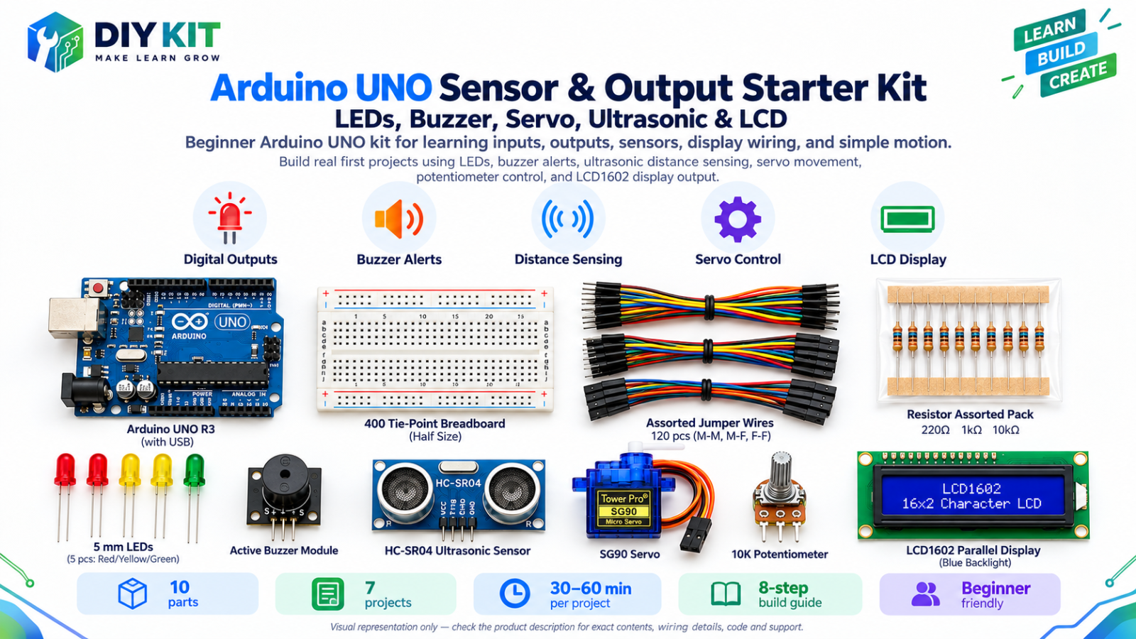
Arduino UNO Sensor & Output Starter Kit - LED… Beginner 10 10 steps AED 85.00
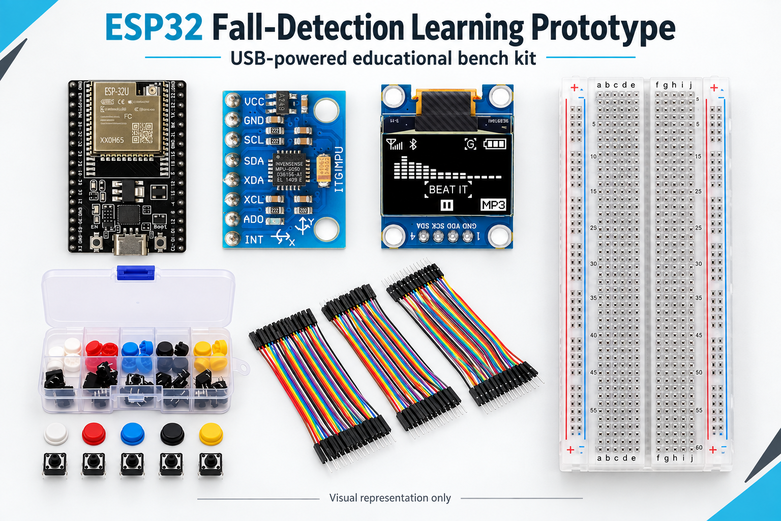
ESP32 Fall-Detection Learning Prototype Intermediate 7 10 steps AED 80.99
ESP32 Plant Monitoring Learning Kit Intermediate 7 14 steps AED 79.00
Distance & Parking Sensor Kit Beginner 9 1 steps On request

Frequently asked

This kit is rated Advanced. You should have built a simple circuit before and be comfortable with breadboard wiring. It is built around the esp32 platform.

3-5 hours; supervised signal experiments extra. The build guide below breaks it into 14 steps.

All 6 components listed in the parts table are packed in the kit. Current availability depends on finished kit stock and component restock status.

Recorded in our catalogue as suited to schools / labs. Bulk pricing is available for classroom sets.

Root
Online — usually replies instantly
Catalog assistant: verify final stock/price on the product page before checkout.