Sharjah, UAE GST
Home/ Kits/ ESP32 Fall-Detection Learning Prototype
Kit Intermediate 90-150 minutes; allow extra time for bench calibration 7 parts 6 projects 10-step build guide

ESP32 Fall-Detection Learning Prototype

AED 80.99 1 built and ready to ship

Buying these 7 parts one by one costs AED 143.21 — the kit saves you AED 62.22 (43%).

Educational bench prototype only. Not a medical device, wheelchair safety system, emergency alarm or substitute for supervision. Firmware is compiler-checked but the hardware, thresholds and detection performance are NOT bench-validated. False alarms and missed events are expected risks. Use USB power only; keep all logic at 3.3 V. Do not connect a 3.7 V cell/TP4056 output to ESP32 VIN, and do not connect the optional 5 V buzzer without a separately reviewed compatible driver. Test only on an unoccupied padded bench rig; never tip, strike or drop a wheelchair or person. Remove power before rewiring. Small parts; recommended age 14+ with adult supervision. No Wi-Fi message, battery check or emergency call is included.

ESP32 Fall-Detection Learning Prototype
KIT-3 · ESP32

Build a USB-powered ESP32 bench prototype that reads a GY-521 IMU, shows local status on an SSD1306 OLED and uses a push button to cancel a 20-second alert countdown. The reviewed sketch detects a high/low acceleration event followed by sustained tilt relative to a startup baseline, and includes a diagnostic mode for button-started countdown checks. Firmware compiles for the recorded ESP32 toolchain, but thresholds, mounting, false alarms and missed events still require physical testing. Educational use only; not a medical, wheelchair-safety or emergency-notification device.

Difficulty
Intermediate
Build time
90-150 minutes; allow extra time for bench calibration
Parts included
7 components
Build guide
10 steps

Included parts (7)

7 parts packed in this kit

Lost or damaged a part? Every part name below opens its own page, so you can buy a replacement or an extra on its own.

Substitutions
Need a part swapped?
Any component here can be substituted — a different board, a larger breadboard, extra sensors for a classroom set.
Ask for a variant

6 projects in this kit

Every one is built from the parts in the box, plus the basics listed under You'll also need.

Basics 01

Fall-Detection Learning Prototype - main documented project

Reads acceleration and orientation relative to a startup baseline. A high- or low-acceleration event followed by sustained tilt starts a local 20-second countdown; the button cancels it. This is an educational bench experiment, not a safety or medical device.

ESP32U GY-521 DIY-003 OLED one DIY-158 tactile switch DIY-212 jumper pack DIY-295 full-size breadboard customer-supplied USB data cable and computer
Parts, guide & add to cart →
Basics 03

Motion Threshold Data Lab - extension

Observe acceleration magnitude and orientation changes for controlled padded-bench motions. Record results before changing any thresholds; a separate logging sketch is required and is not included in the reviewed main firmware.

ESP32U GY-521 DIY-003 OLED DIY-212 jumper pack DIY-295 breadboard
Parts, guide & add to cart →

ESP32 Fall-Detection Learning Prototype

Build, observe and evaluate a local motion-classification experiment

This intermediate learning kit uses an ESP32U, GY-521 motion sensor, SSD1306 OLED and push button to explore acceleration, orientation, event timing and fault handling. The documented build is USB powered and works locally without Wi-Fi, cloud services or a battery.

Verification status: The supplied sketch was compiler-checked on 19 September 2026 in normal and FALL_DIAGNOSTIC modes using ESP32 core 3.3.11. The complete physical circuit has not been bench-tested. Board variant, module pin order, I2C addresses, breadboard continuity, sensor noise, mounting and thresholds must be checked on the actual packed unit.

What the customer will learn

  • How a three-axis accelerometer represents gravity and sudden motion.
  • How to share one 3.3 V I2C bus between a GY-521 and SSD1306 OLED.
  • How to establish a startup orientation baseline and calculate angle from that baseline.
  • Why a single impact reading is not enough to identify a fall-like event.
  • How a candidate window, sustained-tilt timer, countdown and acknowledgement state work together.
  • How diagnostic modes, serial logs and fault states make an embedded project easier to test.
  • How to record false positives and false negatives instead of assuming a prototype is reliable.

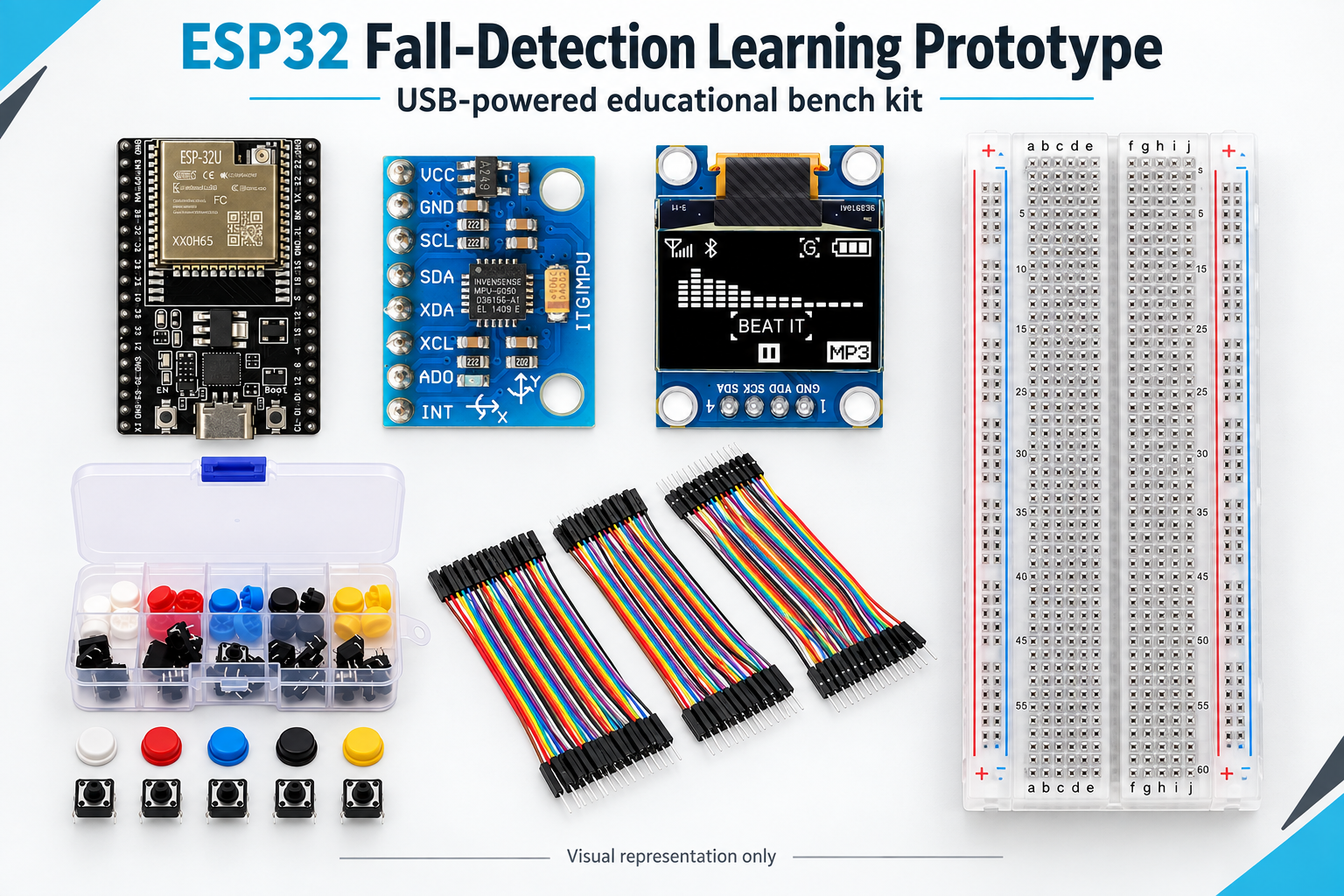
What is included

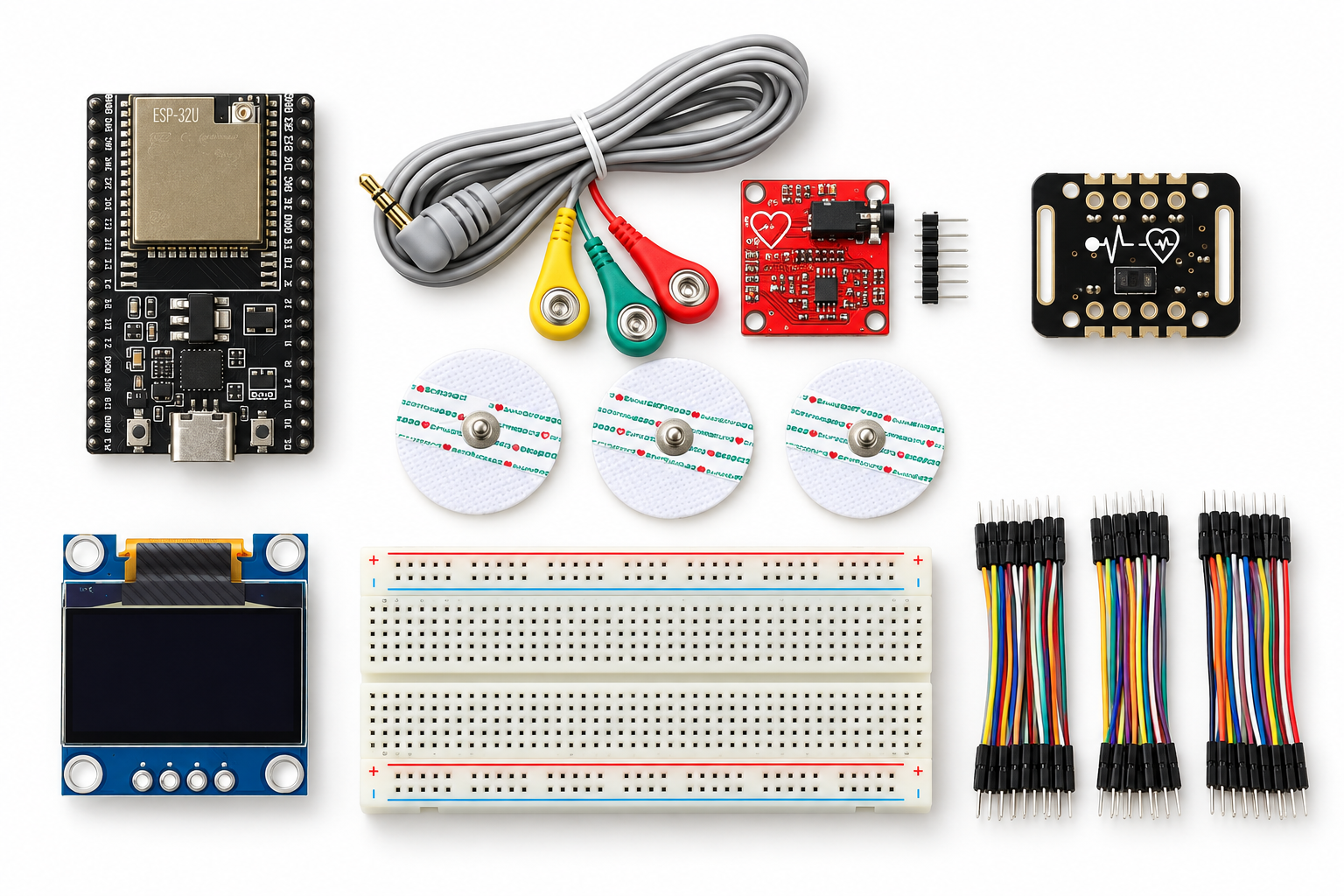
Catalogue itemQuantityPurpose in the main projectImportant check
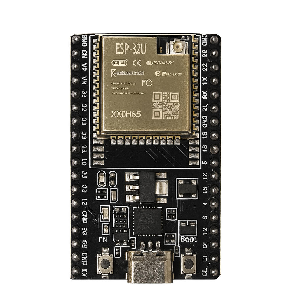
ESP32U development board1Runs the firmware, reads the sensor, drives the OLED and handles the button.Confirm the exact original ESP32 board, USB connector and GPIO labels. This pin plan is not for C3, S2 or S3 variants.
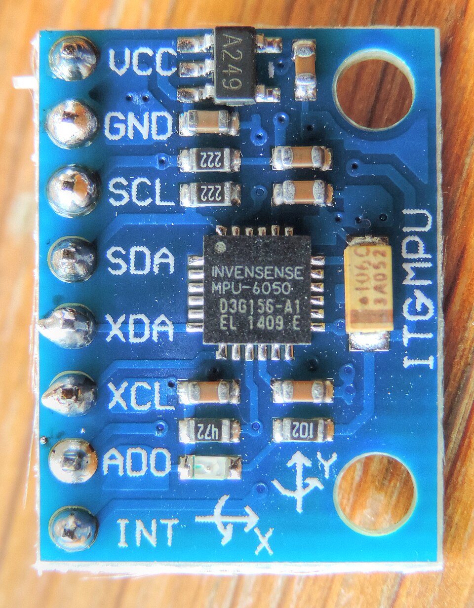
GY-521 MPU-6050 module1Provides three-axis acceleration readings for impact and orientation calculations.Use 3.3 V. Confirm the physical pin order and exactly one I2C address at 0x68 or 0x69.
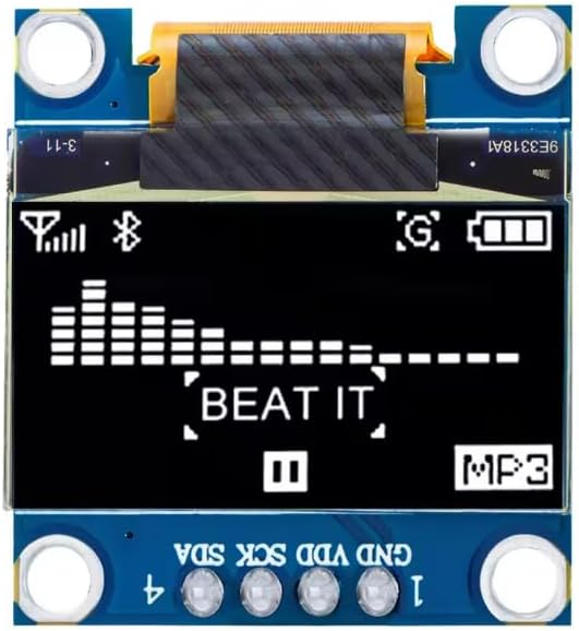
DIY-003 SSD1306 128x64 I2C OLED1Shows calibration, monitoring, countdown, alert and fault states.Use 3.3 V. Confirm the pin order, pull-ups and exactly one address at 0x3C or 0x3D.
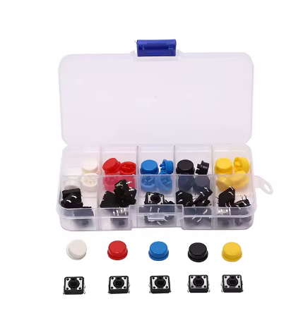
DIY-158 tactile-switch assortment1 packOne momentary switch provides cancel and acknowledge input.Identify the two internally common pin pairs with a meter. Only one switch is consumed by the main build.
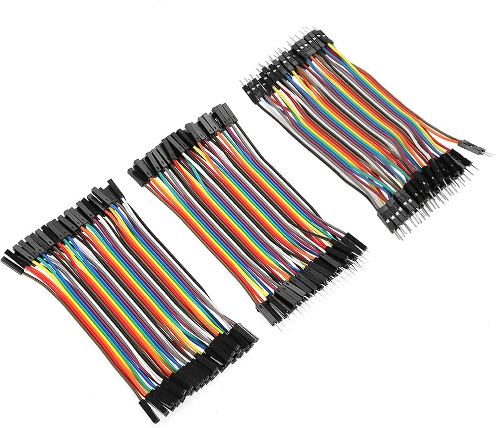
DIY-212 mixed jumper-wire assortment1 packProvides male-to-male, male-to-female and female-to-female low-current signal leads.Choose leads that match the actual headers and check every contact before power.
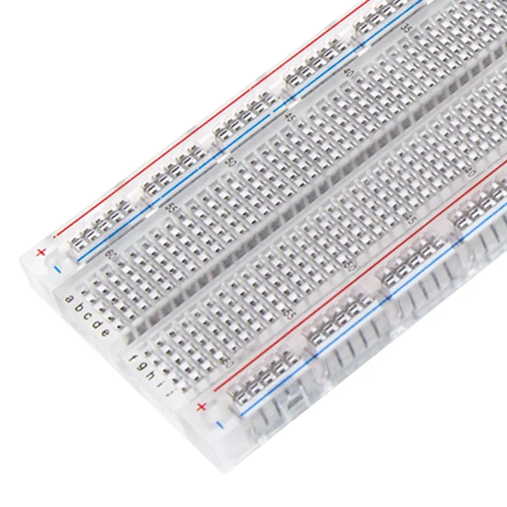
DIY-295 transparent full-size 830-point breadboard1Provides a large solderless area for the 3.3 V signal circuit.Check split power rails, continuity and ESP32 clearance. Mount the ESP32 beside the board if it blocks usable holes.

Optional catalogue add-on: DIY-016 is a 5 V active buzzer module. It is not connected or supported by the reviewed main firmware. Its input topology, current and 3.3 V trigger compatibility must be measured before a suitable driver, protection and power arrangement can be selected.

What the customer must supply

  • A computer running Arduino IDE or Arduino CLI.
  • A USB data cable that matches the actual ESP32U connector; a charge-only cable will not upload firmware.
  • A digital multimeter for continuity, rail-voltage and switch-terminal checks.
  • A non-conductive work surface and a padded, unoccupied lightweight test platform.
  • Removable tape, ties or other non-metal mounting materials for controlled bench tests.
  • A notebook or spreadsheet for recording addresses, thresholds, resets, false triggers and missed events.
  • Optional ESD protection and eye protection for inspection work.
  • Soldering iron, solder, stand, ventilation and eye protection only if the supplied modules have unsoldered headers. Learners require competent adult supervision.

No battery, charger, mobile phone, Telegram account or Wi-Fi connection is required for the documented main project.

Time and difficulty: Allow about 90 to 150 minutes for inspection, wiring, software setup and diagnostic checks. Threshold study and repeatable physical calibration take additional time. This is an intermediate kit for supervised learners aged 14+ or adults who can identify board pins, use a meter and read serial output.

How the detection experiment works

  1. Device discovery: At startup the firmware accepts exactly one OLED at 0x3C or 0x3D and exactly one MPU at 0x68 or 0x69. Ambiguous or missing devices cause a fault.
  2. Baseline calibration: The platform must remain still in its normal reference orientation for approximately three seconds while 150 acceleration samples are collected. Samples outside 0.75 g to 1.25 g cause calibration failure.
  3. Monitoring: The firmware samples acceleration approximately every 20 ms and calculates acceleration magnitude plus angle from the startup gravity vector.
  4. Candidate event: A reading above 2.5 g or below 0.45 g opens a five-second candidate window.
  5. Sustained orientation change: During that window, an angle of at least 55 degrees must persist for 1.5 seconds before a countdown begins.
  6. Local countdown: The OLED shows a 20-second countdown. A fresh press on the GPIO26 button cancels it.
  7. Local alert: If the countdown expires, the OLED shows LOCAL ALERT and the board LED flashes only if the exact board has a usable LED on GPIO2. No remote message or emergency call is made.
  8. Fault handling: Five consecutive MPU read failures latch a fault. Remove power and inspect the circuit rather than continuing with uncertain data.

These values are starting points for an educational experiment. They are not validated fall criteria and must not be presented as safety performance.

Power rule: Power the ESP32U through its matching USB data cable only. Power the GY-521 and OLED from ESP32 3V3 and GND. Do not connect a single-cell Li-ion battery or TP4056 output directly to ESP32 VIN/5V. Disconnect USB before moving any wire.

Main-project wiring reference

The connection names below are GPIO numbers printed on a compatible original ESP32 board, not physical connector positions. Confirm every label on the actual board and every module before wiring.

PartTerminalConnect toVerification
ESP32UUSBComputer through matching USB data cableSelect the exact port and original ESP32 Dev Module target.
DIY-003 OLEDVCCESP32 3V3Confirm the module pin order before power.
DIY-003 OLEDGNDESP32 GNDCheck continuity to the ground rail.
DIY-003 OLEDSDAGPIO21Shared I2C data line with GY-521.
DIY-003 OLEDSCLGPIO22Shared I2C clock line with GY-521.
GY-521VCCESP32 3V3Do not use the 5 V rail in this documented build.
GY-521GNDESP32 GNDShare the same ground as the OLED and button.
GY-521SDAGPIO21Confirm one address at 0x68 or 0x69.
GY-521SCLGPIO22Keep leads short and secure for the first tests.
Tactile switchOne switched sideGPIO26Firmware uses INPUT_PULLUP; no external pull-up is required.
Tactile switchOpposite switched sideGNDUse one leg from each switched pair, not two permanently common legs.
Onboard LEDBoard-specificGPIO2 in the supplied sketchOptional indicator only. Some ESP32U variants have no usable LED here.

Software versions used for the compile check

SoftwareReviewed versionWhy it is needed
ESP32 core by Espressif Systems3.3.11Board support and ESP32 APIs.
Adafruit SSD13062.5.17OLED control.
Adafruit GFX1.12.6Text and graphics used by the OLED library.
Adafruit BusIO1.17.4Dependency used by the display libraries.

The sketch reads MPU-6050 acceleration registers directly over Wire, so no separate MPU library is required. Open Serial Monitor at 115200 baud for device addresses, candidate events, button activity and fault messages.

Fourteen-stage build and check sequence

  1. Confirm scope and inventory

    Lay out the six required catalogue products and the customer-supplied USB cable and meter. Keep the optional 5 V buzzer, batteries, chargers and unrelated modules away from the main build. Check for bent pins, damaged insulation or unsoldered headers.

  2. Prepare the reviewed toolchain

    Install ESP32 core 3.3.11 plus Adafruit SSD1306 2.5.17, GFX 1.12.6 and BusIO 1.17.4. Select ESP32 Dev Module only after confirming the board is the compatible original ESP32 type.

  3. Check board, cable and breadboard

    With USB disconnected, identify 3V3, GND, GPIO21, GPIO22 and GPIO26. Confirm the USB cable carries data. Use the meter to find any split breadboard rails and mark the sections that must be linked.

  4. Build the 3.3 V and ground rails

    Connect ESP32 3V3 to the chosen positive rail and ESP32 GND to the ground rail. Do not connect USB yet. Measure resistance between the rails and stop if a short is indicated.

  5. Add the OLED

    Confirm the module pin order, then connect VCC to 3V3, GND to GND, SDA to GPIO21 and SCL to GPIO22. Do not assume every four-pin OLED uses the same left-to-right order.

  6. Add the GY-521

    Confirm its pin labels, then connect VCC to 3V3, GND to GND, SDA to GPIO21 and SCL to GPIO22 in parallel with the OLED. Leave XDA, XCL, AD0 and INT unconnected for the reviewed main build.

  7. Add the cancel button

    Use continuity mode to identify the two permanently common pin pairs. Place the switch so one leg from each switched side is used. Connect one side to GPIO26 and the other to GND.

  8. Perform the unpowered inspection

    Trace every path against the wiring table. Check 3V3 and GND polarity, module pin order, breadboard rail breaks, loose jumper ends and accidental contact between adjacent pins. Only then connect USB.

  9. Upload diagnostic mode

    Set FALL_DIAGNOSTIC to true, click Verify, then Upload. Keep the platform still through startup. Serial Monitor should report one OLED address and one MPU address. A missing or ambiguous device must produce a fault rather than silent operation.

  10. Verify low-power inputs and states

    Press and release the button once to start a countdown. Release fully, then press again to cancel. Repeat several times to check debounce and contact reliability. Confirm the OLED is readable and the board does not reset or heat.

  11. Upload normal mode

    Set FALL_DIAGNOSTIC back to false, Verify and Upload again. Keep the platform still in its intended reference orientation for the three-second calibration. The OLED should reach MONITORING.

  12. Test the motion rule safely

    Secure the electronics to a lightweight, unoccupied platform over a thick foam mat. Use controlled movements only. Record acceleration and orientation behaviour; do not drop, strike or attach the prototype to a person or wheelchair.

  13. Check countdown, cancel and alert

    When a controlled motion meets the nominal rule, verify the 20-second countdown. Confirm a fresh button press cancels it. In a separate run, allow it to expire and verify LOCAL ALERT appears. Acknowledge with the button. No remote message should be expected.

  14. Record limitations and failure cases

    Test ordinary bumps, slow tilts, restarts, held button, missing OLED, missing MPU and temporary I2C interruptions. Record false positives, false negatives, resets, heat and loose-contact symptoms. Keep the template under review until the actual unit and thresholds have a documented test record.

Expected OLED and serial states

StateWhat it meansCustomer action
KEEP STILL AND LEVELThe three-second startup baseline is being measured.Do not move the test platform.
MONITORINGThe sensor is being sampled locally.Observe readings and begin only controlled tests.
POSSIBLE EVENTThe motion rule started the 20-second countdown.Press and release the button to cancel, or allow a planned test to continue.
CANCELLEDThe user cancelled the countdown.Confirm monitoring resumes.
LOCAL ALERTThe countdown expired.Press the button to acknowledge. Remember that no message was sent.
FAULT - POWER OFFDiscovery, calibration or repeated sensor reads failed.Disconnect USB and inspect wiring, addresses and movement during calibration.

Recommended physical test record

TestRepeatRecordPassing observation for this learning prototype
Cold startup10 timesDetected addresses, calibration result, resetsEvery planned run reaches MONITORING without unexplained reset.
Diagnostic countdown10 timesStart, cancel and debounce behaviourOne press starts; one fresh press cancels; held contact does not repeat.
Ordinary handlingAt least 20 motionsFalse countdownsResults are documented; any false trigger leads to threshold/mounting review.
Planned candidate motionsAt least 10 motionsCandidate, tilt hold, countdown and missed eventsResults are documented; misses are not hidden or described as successful detection.
Long run30 to 60 minutesHeat, resets, OLED faults and I2C errorsNo unsafe heat or unexplained failure; any issue is investigated before reuse.
Fault injectionOne controlled test per deviceMissing-device and read-failure responseThe prototype stops in a clear fault state rather than claiming normal monitoring.

The repeat counts above are a practical classroom test plan, not a certification standard. They do not establish medical, safety or commercial reliability.

Troubleshooting

SymptomLikely checkSafe next step
No serial portCharge-only cable, driver, wrong connector or damaged boardTry a known data cable and confirm the exact board before changing wiring.
Need one OLED and one MPUMissing device, wrong address, reversed pins or bus shortDisconnect USB, inspect pin order and scan the bus with one module connected at a time.
Calibration failedPlatform moved, sensor is loose or acceleration magnitude is outside the accepted rangeSecure the sensor, place the rig still in its reference orientation and restart.
Button does nothingBoth leads are on one permanently common side or GPIO/GND is incorrectDisconnect power and map the switch terminals with continuity mode.
Repeated false countdownsLoose mounting, vibration, noisy power or unsuitable thresholdsStop the test, secure the assembly and record data before changing one threshold at a time.
Missed planned eventsMotion did not cross both stages, tilt duration was short or baseline orientation changedReview the serial log and controlled test method; never claim reliability from a single pass.
ESP32 resets or becomes hotShort, reversed power, unstable contact or damaged hardwareDisconnect USB immediately and inspect with a meter. Do not continue until the cause is known.

Suggested extensions and their limits

Motion Threshold Data Lab: Create a separate logging sketch to capture acceleration magnitude and angle during controlled motions. Logging code is not included in the reviewed main sketch.

Orientation Calibration Study: Compare stable startup positions and mounting directions to see how the baseline gravity vector changes the calculated angle. Use a rigid unoccupied test fixture.

Optional Audible Alert Investigation: First measure the DIY-016 module input and current. Add only a separately reviewed 3.3 V-compatible driver, protection and power path. The main firmware does not support this extension.

Secure Remote Notification Study: Treat networking as a separate project requiring authenticated communications, privacy review, service-failure handling and a non-device fallback plan. Wi-Fi, Telegram, credentials and delivery confirmation are not included here.

Understand before buying

  • This is a parts-based educational prototype, not a preassembled or calibrated safety product.
  • The main project provides local OLED and optional board-LED feedback only.
  • It does not contact a caregiver, monitor battery health or call emergency services.
  • It must not be used as a medical device, wheelchair safety system or substitute for supervision.
  • The firmware compiles, but actual hardware behaviour depends on the exact board and modules packed.
  • The wiring diagram remains hidden until the physical pin mapping is checked on a real unit.
  • The customer should expect to inspect, wire, upload, test, record results and adjust the experiment under supervision.
Final safety note: Test only on an unoccupied padded bench rig. Never drop, tip or strike a wheelchair or person. Remove USB before rewiring. Keep all documented module power at 3.3 V, use USB power only for the ESP32U, and leave the optional 5 V buzzer disconnected until its interface is separately verified.

Build steps (10)

Tick steps off as you go — your place is kept on this device.

0 / 10
These steps come from the build reference recorded for this kit. The firmware is in the Code section below.

Code

The sketch we ship with this kit. Copy it, or ask us for the version matched to your board.

1
271
arduino
Main sketch (FallDetectionLearningPrototype.ino)
#include <Arduino.h>
#include <Wire.h>
#include <Adafruit_GFX.h>
#include <Adafruit_SSD1306.h>

// Educational bench prototype. Not a medical, emergency or life-safety device.
#ifndef FALL_DIAGNOSTIC
#define FALL_DIAGNOSTIC false
#endif

constexpr uint8_t SDA_PIN = 21;
constexpr uint8_t SCL_PIN = 22;
constexpr uint8_t BUTTON_PIN = 26;
constexpr uint8_t LED_PIN = 2;  // Common ESP32 Dev Module onboard LED; verify board.
constexpr uint32_t SAMPLE_MS = 20;
constexpr uint32_t DEBOUNCE_MS = 35;
constexpr uint32_t CANDIDATE_MS = 5000;
constexpr uint32_t TILT_HOLD_MS = 1500;
constexpr uint32_t COUNTDOWN_MS = 20000;
constexpr uint32_t DISPLAY_MS = 250;
constexpr float IMPACT_G = 2.5f;
constexpr float FREEFALL_G = 0.45f;
constexpr float TILT_DEG = 55.0f;

Adafruit_SSD1306 display(128, 64, &Wire, -1, 100000, 100000);

enum class State { Monitoring, Candidate, Countdown, Alert, Fault };
State state = State::Fault;
uint8_t mpuAddress = 0, oledAddress = 0;
float baseX = 0, baseY = 0, baseZ = 1;
uint32_t stateSince = 0, tiltSince = 0, lastSample = 0, lastDisplay = 0;
uint32_t events = 0;
uint8_t readFailures = 0;
bool rawButton = HIGH, stableButton = HIGH, buttonArmed = false;
uint32_t rawSince = 0;

bool elapsed(uint32_t now, uint32_t since, uint32_t interval) {
  return uint32_t(now - since) >= interval;
}

bool i2cAck(uint8_t address) {
  Wire.beginTransmission(address);
  return Wire.endTransmission() == 0;
}

bool writeRegister(uint8_t reg, uint8_t value) {
  Wire.beginTransmission(mpuAddress);
  Wire.write(reg);
  Wire.write(value);
  return Wire.endTransmission() == 0;
}

bool readAccel(float &x, float &y, float &z) {
  Wire.beginTransmission(mpuAddress);
  Wire.write(0x3B);
  if (Wire.endTransmission(false) != 0) return false;
  if (Wire.requestFrom(int(mpuAddress), 6) != 6) return false;
  int16_t rx = int16_t((uint16_t(Wire.read()) << 8) | Wire.read());
  int16_t ry = int16_t((uint16_t(Wire.read()) << 8) | Wire.read());
  int16_t rz = int16_t((uint16_t(Wire.read()) << 8) | Wire.read());
  x = rx / 4096.0f;
  y = ry / 4096.0f;
  z = rz / 4096.0f;
  return true;
}

void show(const __FlashStringHelper *line1, const String &line2 = "") {
  display.clearDisplay();
  display.setTextColor(SSD1306_WHITE);
  display.setTextSize(1);
  display.setCursor(0, 0);
  display.println(F("FALL-DETECTION LAB"));
  display.println(F("TRAINING ONLY"));
  display.println();
  display.println(line1);
  display.println(line2);
  display.display();
}

void fault(const __FlashStringHelper *reason) {
  state = State::Fault;
  digitalWrite(LED_PIN, HIGH);
  Serial.print(F("FAULT: "));
  Serial.println(reason);
  if (oledAddress && i2cAck(oledAddress)) show(F("FAULT - POWER OFF"), String(reason));
}

bool initialiseDevices() {
  bool oled3c = i2cAck(0x3C), oled3d = i2cAck(0x3D);
  if (oled3c == oled3d) return false;
  oledAddress = oled3c ? 0x3C : 0x3D;
  if (!display.begin(SSD1306_SWITCHCAPVCC, oledAddress, true, false)) return false;

  bool mpu68 = i2cAck(0x68), mpu69 = i2cAck(0x69);
  if (mpu68 == mpu69) return false;
  mpuAddress = mpu68 ? 0x68 : 0x69;
  if (!writeRegister(0x6B, 0x01)) return false;
  delay(50);
  if (!writeRegister(0x1C, 0x10)) return false;
  if (!writeRegister(0x1A, 0x04)) return false;
  Serial.printf("OLED=0x%02X MPU=0x%02X\n", oledAddress, mpuAddress);
  return true;
}

bool calibrateBaseline() {
  show(F("KEEP STILL AND LEVEL"), F("Calibrating 3 seconds"));
  float sx = 0, sy = 0, sz = 0;
  constexpr int samples = 150;
  for (int i = 0; i < samples; ++i) {
    float x, y, z;
    if (!readAccel(x, y, z)) return false;
    float mag = sqrtf(x * x + y * y + z * z);
    if (mag < 0.75f || mag > 1.25f) return false;
    sx += x; sy += y; sz += z;
    delay(20);
  }
  float mag = sqrtf(sx * sx + sy * sy + sz * sz);
  if (mag < 0.001f) return false;
  baseX = sx / mag; baseY = sy / mag; baseZ = sz / mag;
  return true;
}

float angleFromBaseline(float x, float y, float z, float mag) {
  if (mag < 0.001f) return 180.0f;
  float dot = (x * baseX + y * baseY + z * baseZ) / mag;
  return acosf(constrain(dot, -1.0f, 1.0f)) * 180.0f / PI;
}

bool pressedEdge(uint32_t now) {
  bool reading = digitalRead(BUTTON_PIN);
  if (reading != rawButton) {
    rawButton = reading;
    rawSince = now;
  }
  bool edge = false;
  if (reading != stableButton && elapsed(now, rawSince, DEBOUNCE_MS)) {
    stableButton = reading;
    edge = stableButton == LOW;
    Serial.println(edge ? F("Button pressed") : F("Button released"));
  }
  if (stableButton == HIGH && rawButton == HIGH && elapsed(now, rawSince, DEBOUNCE_MS))
    buttonArmed = true;
  if (edge && buttonArmed) {
    buttonArmed = false;
    return true;
  }
  return false;
}

void enterCountdown(uint32_t now, const __FlashStringHelper *source) {
  state = State::Countdown;
  stateSince = now;
  ++events;
  Serial.print(F("Countdown started: "));
  Serial.println(source);
  show(F("EVENT? 20 SECONDS"), F("Press button to cancel"));
}

void setup() {
  Serial.begin(115200);
  pinMode(BUTTON_PIN, INPUT_PULLUP);
  pinMode(LED_PIN, OUTPUT);
  digitalWrite(LED_PIN, LOW);
  rawButton = stableButton = digitalRead(BUTTON_PIN);
  rawSince = millis();
  if (!Wire.begin(SDA_PIN, SCL_PIN, 100000)) {
    fault(F("I2C start failed"));
    return;
  }
  Wire.setTimeOut(20);
  if (!initialiseDevices()) {
    fault(F("Need one OLED and one MPU"));
    return;
  }
  if (!calibrateBaseline()) {
    fault(F("Calibration failed"));
    return;
  }
  state = State::Monitoring;
  stateSince = millis();
  show(F("MONITORING"), FALL_DIAGNOSTIC ? F("Button starts test") : F("Local demo only"));
  Serial.println(F("No Wi-Fi, Telegram, buzzer, battery measurement or emergency guarantee."));
}

void loop() {
  uint32_t now = millis();
  bool button = pressedEdge(now);
  if (state == State::Fault) return;

  if (button && state == State::Countdown) {
    state = State::Monitoring;
    stateSince = now;
    digitalWrite(LED_PIN, LOW);
    show(F("CANCELLED"), F("Monitoring resumed"));
    Serial.println(F("Countdown cancelled"));
    return;
  }
  if (button && state == State::Alert) {
    state = State::Monitoring;
    stateSince = now;
    digitalWrite(LED_PIN, LOW);
    show(F("ACKNOWLEDGED"), F("Monitoring resumed"));
    Serial.println(F("Local alert acknowledged"));
    return;
  }
  if (button && FALL_DIAGNOSTIC && state == State::Monitoring) {
    enterCountdown(now, F("diagnostic button"));
    return;
  }

  if (state == State::Countdown) {
    uint32_t used = now - stateSince;
    if (used >= COUNTDOWN_MS) {
      state = State::Alert;
      stateSince = now;
      show(F("LOCAL ALERT"), F("Press to acknowledge"));
      Serial.println(F("LOCAL ALERT ONLY - no message was sent"));
      return;
    }
    digitalWrite(LED_PIN, ((now / 300) & 1) ? HIGH : LOW);
    if (elapsed(now, lastDisplay, DISPLAY_MS)) {
      lastDisplay = now;
      uint32_t seconds = (COUNTDOWN_MS - used + 999) / 1000;
      show(F("POSSIBLE EVENT"), String(seconds) + F(" s - press to cancel"));
    }
    return;
  }
  if (state == State::Alert) {
    digitalWrite(LED_PIN, ((now / 150) & 1) ? HIGH : LOW);
    return;
  }
  if (!elapsed(now, lastSample, SAMPLE_MS)) return;
  lastSample = now;

  float x, y, z;
  if (!readAccel(x, y, z)) {
    if (++readFailures >= 5) fault(F("MPU read failed"));
    return;
  }
  readFailures = 0;
  float mag = sqrtf(x * x + y * y + z * z);
  float tilt = angleFromBaseline(x, y, z, mag);

  if (state == State::Monitoring) {
    if (mag > IMPACT_G || mag < FREEFALL_G) {
      state = State::Candidate;
      stateSince = now;
      tiltSince = 0;
      Serial.printf("Candidate: %.2f g, %.1f deg\n", mag, tilt);
    } else if (elapsed(now, lastDisplay, 1000)) {
      lastDisplay = now;
      show(F("MONITORING"), String(mag, 2) + F(" g  events ") + events);
    }
    return;
  }

  if (state == State::Candidate) {
    if (elapsed(now, stateSince, CANDIDATE_MS)) {
      state = State::Monitoring;
      tiltSince = 0;
      show(F("NO EVENT"), F("Monitoring resumed"));
      return;
    }
    if (tilt >= TILT_DEG) {
      if (tiltSince == 0) tiltSince = now;
      if (elapsed(now, tiltSince, TILT_HOLD_MS)) enterCountdown(now, F("motion rule"));
    } else {
      tiltSince = 0;
    }
  }
}
Pin numbers and thresholds are written for the board in this kit. Change the board and the pin map changes with it — ask and we'll adjust it.

What this kit teaches

A wheelchair-mounted fall detection device. A motion sensor (MPU6050) detects a hard impact or free-fall followed by sustained tilt, then sounds a buzzer alarm and starts a 20-second countdown on the OLED display. If the user presses the snooze button it cancels; if not, an alert is sent directly to the caregiver's phone via Telegram. Also sends a daily "device OK" heartbeat so a flat battery is never missed. Runs on a rechargeable 18650 battery so it moves with the chair. Assistive aid, not a medical device.

Difficulty · Intermediate

Assumes you have built a simple circuit before and can follow a wiring guide. You will install a toolchain and upload code.

You'll also need
  • Computer with Arduino IDE or Arduino CLI
  • USB data cable that matches the actual ESP32U connector
  • Digital multimeter for continuity and voltage checks
  • Insulating mat or non-conductive work surface
  • Padded foam or soft unoccupied bench rig for controlled motion tests
  • Removable tape, ties or fasteners for securing modules during bench tests
  • Notebook or spreadsheet for recording thresholds, false triggers and missed events
  • Adult supervision for learners under 14
  • Optional: ESD protection and eye protection for inspection work
Who it's for

Catalogued as suited to classroom. Built around Customer request - WhatsApp +971 55 558 8588 hardware. Classroom sets are quoted per seat — ask for a bulk price.

How it compares

KitLevelPartsBuild guidePrice
This kit ESP32 Fall-Detection Learning Prototype Intermediate 7 10 steps AED 80.99
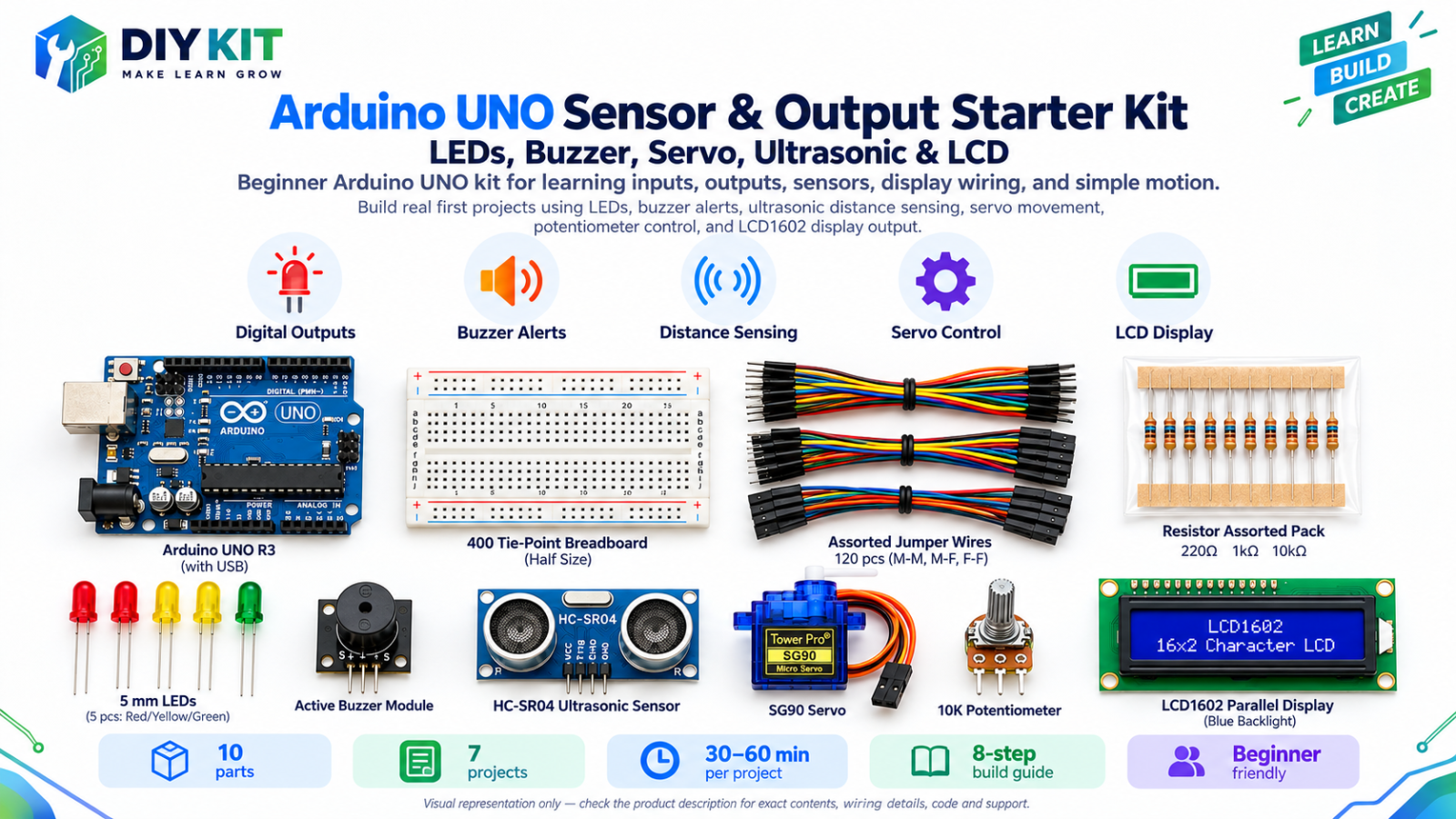
Arduino UNO Sensor & Output Starter Kit - LED… Beginner 10 10 steps AED 85.00
Biomedical Sensor & Bio-Signal Learning Kit Intermediate 6 7 steps AED 101.50
ESP32 Plant Monitoring Learning Kit Intermediate 7 14 steps AED 79.00
Distance & Parking Sensor Kit Beginner 9 1 steps On request

Frequently asked

This kit is rated Intermediate. You should have built a simple circuit before and be comfortable with breadboard wiring. It is built around the esp32 platform.

90-150 minutes; allow extra time for bench calibration. The build guide below breaks it into 10 steps.

All 7 components listed in the parts table are packed in the kit. Current availability depends on finished kit stock and component restock status.

Recorded in our catalogue as suited to classroom. Bulk pricing is available for classroom sets.

Root
Online — usually replies instantly
Catalog assistant: verify final stock/price on the product page before checkout.