Build guide - ESP32 - Intermediate
ESP32 Plant Monitoring Learning Kit
Build a USB-powered learning prototype that calibrates two analog sensors, identifies a BME280, stores reference points, and reports local plant and room data in Serial Monitor.
7 learning projects6 required catalog items90-150 minutes3.3 V logic
01What you will build
Main learning build
The ESP32 reads a capacitive soil sensor on GPIO34, a short-duration conductive water sensor on GPIO35, and a 3.3 V BME280 on the GPIO21/22 I2C bus. The supplied program averages measurements, guides calibration, stores four endpoints in non-volatile memory, and prints data every two seconds.
Clear scope
This is not an automatic irrigation controller, weatherproof product, calibrated scientific instrument, plant-care guarantee, or unattended alarm. No pump, valve, relay, enclosure, battery, cloud service, Wi-Fi dashboard, or verified buzzer driver is part of the main build.
Verification level. The firmware was compiler-checked for the ESP32 target in normal and diagnostic modes. The exact catalog parts, physical pin labels, board fit, signal voltages, sensor accuracy, and assembled wiring have not been bench-tested together. Complete the release checklist before describing the kit as physically verified.
02What is included
| Qty | Catalog item | Purpose |
|---|
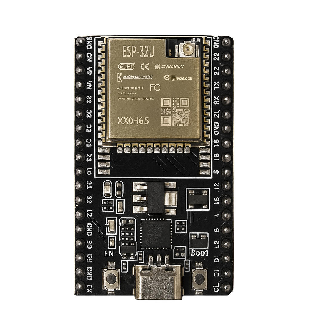
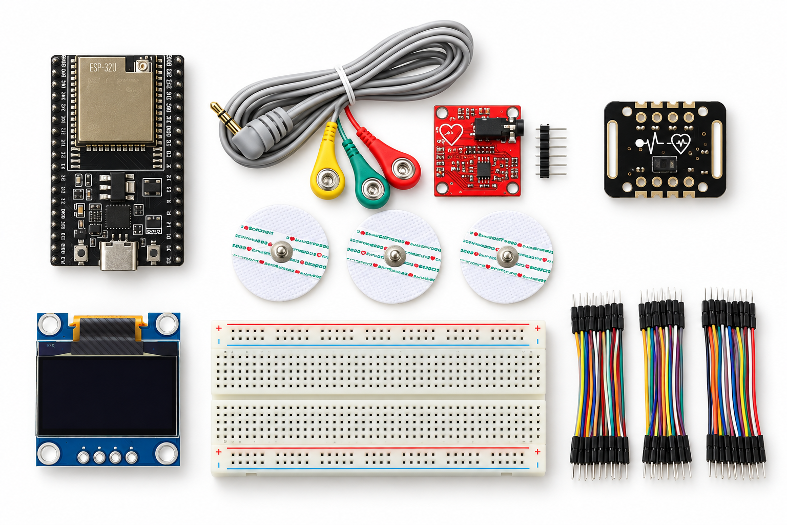
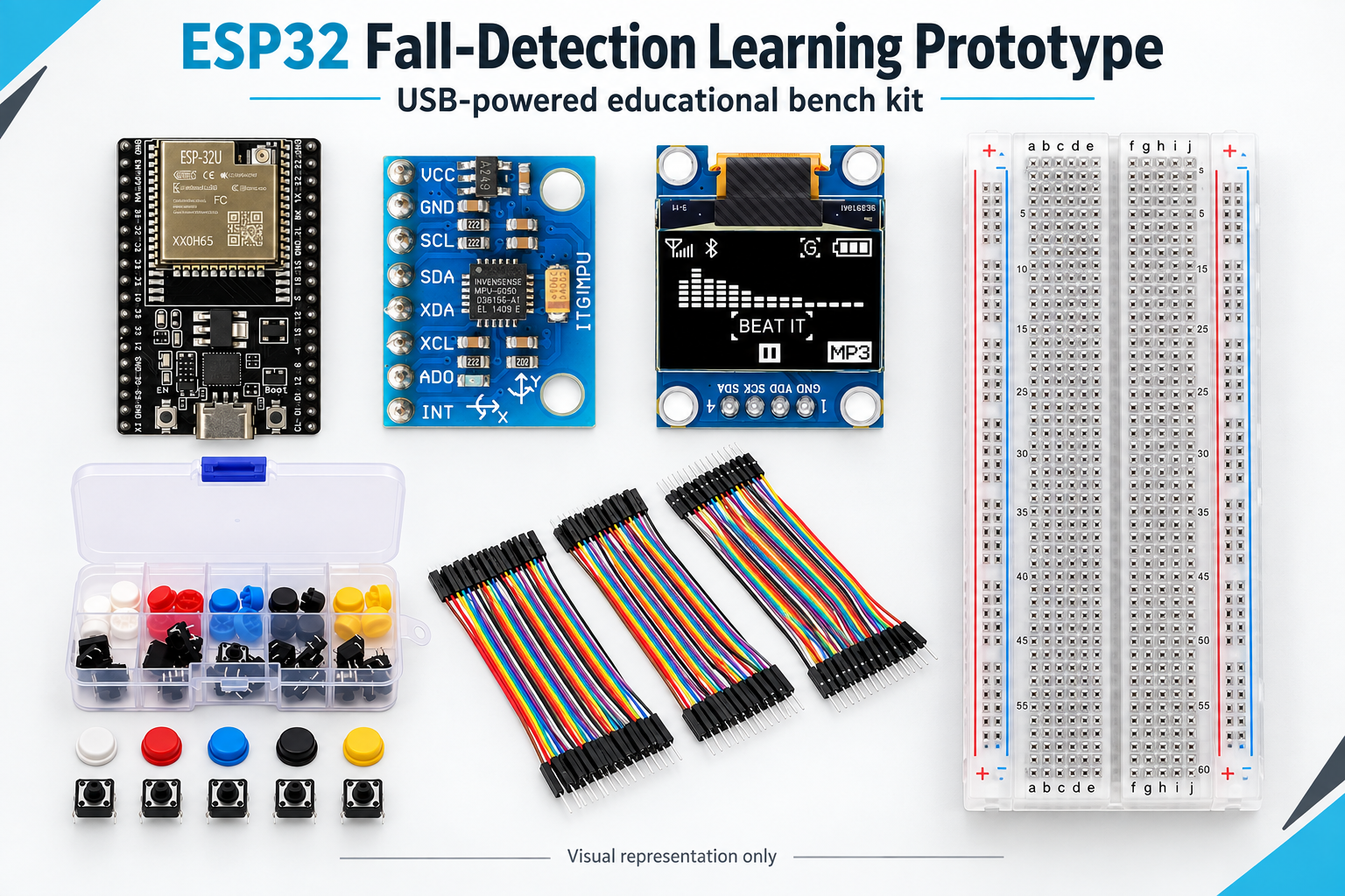
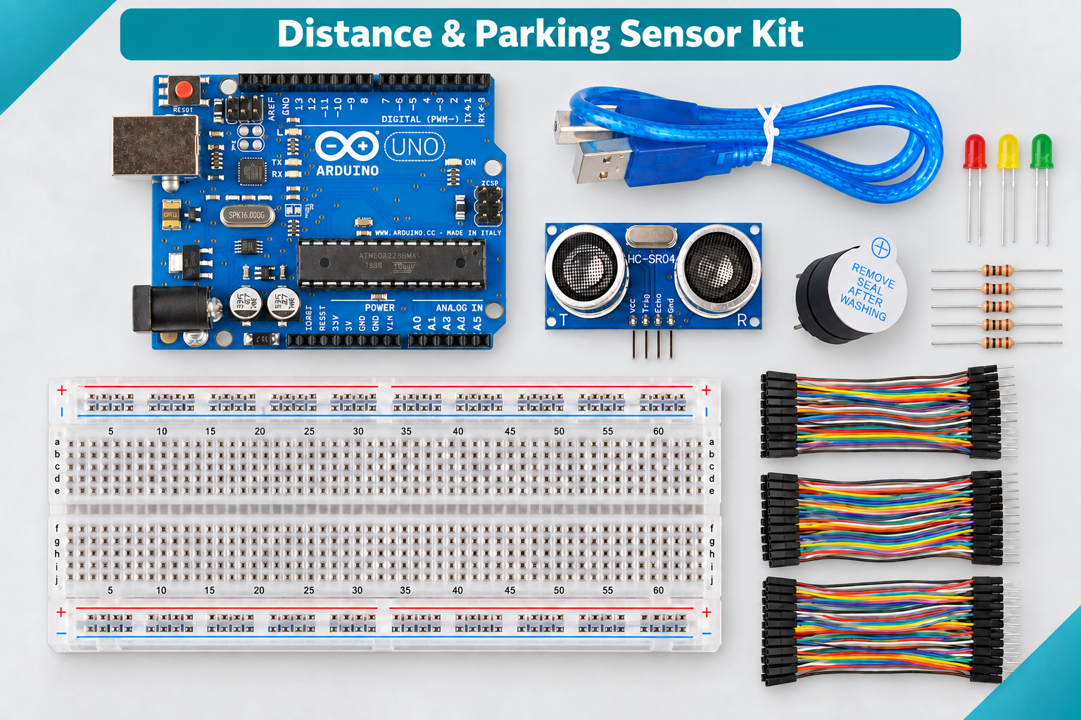
| 1 | ESP32U development board | Main controller, USB programming, two ADC1 inputs, and I2C. |
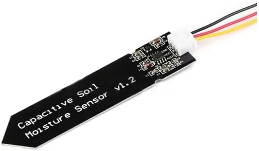
| 1 | DIY-002 capacitive soil moisture sensor v2.0 | Analog soil reference. Calibrate it in your own dry and wet materials. |
| 1 | DIY-025 conductive water-level sensor | Brief supervised water-contact experiment only; rinse and dry after use. |
| 1 | DIY-018 BME280 module | 3.3 V I2C temperature, humidity, and pressure readings. |
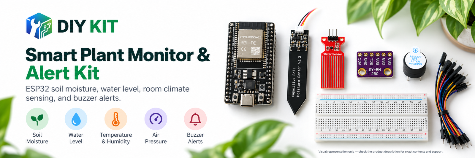
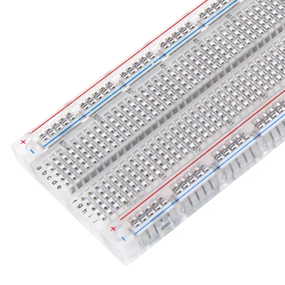
| 1 | DIY-295 full-size 830-point breadboard | More working room than a half-size board for the wide ESP32 and sensor wiring. |
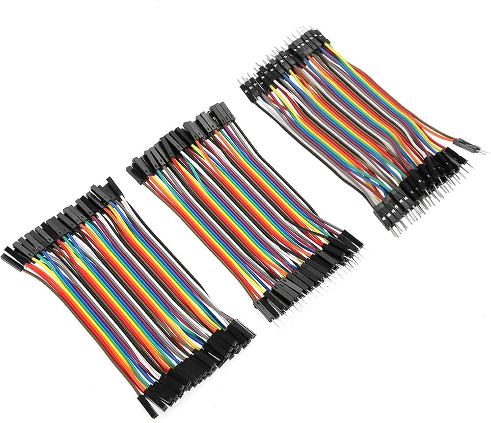
| 1 pack | DIY-212 assorted jumper wires | Male-to-male, male-to-female, and female-to-female connections. |
Optional extension: DIY-016 5 V active buzzer. It is not driven by the checked main firmware. Before connecting it, measure or confirm module current, trigger threshold, active-high/active-low behavior, and a suitable transistor or driver stage. Never put 5 V on an ESP32 GPIO.
03What you also need
Computer and software
Computer with Arduino IDE 2.x, Arduino-ESP32 board support, Adafruit BME280, Adafruit Unified Sensor, and Adafruit BusIO libraries, plus permission to install them.
USB and test references
A known-good USB-C data cable, dry and wet soil references, a shallow non-metallic container, a small amount of clean water, labels, notebook, and spreadsheet software if you want charts.
Safety and cleanup
Dry work tray, paper towels, clean rinse water, eye protection, and adult supervision for learners under 14.
Recommended test tool
A digital multimeter for checking 3.3 V, ground continuity, rail breaks, and analog signal voltage before an ESP32 GPIO is connected.
A soldering iron, solder, stand, ventilation, and supervision are needed only if a supplied module arrives with loose headers. Never solder a powered circuit.
04Reviewed pin plan
Disconnect USB before changing wires. Verify the labels printed on the exact modules because pin order can vary between revisions. Power all three required sensors from the ESP32 3V3 pin and join every ground.
| Part pin | ESP32U | Purpose and check |
|---|
| DIY-002 VCC | 3V3 | Keeps the analog output in the ESP32 voltage domain. |
| DIY-002 GND | GND | Common reference. |
| DIY-002 AOUT | GPIO34 | Input-only ADC1 pin; verify signal remains 0-3.3 V. |
| DIY-025 + / VCC | 3V3 | Use 3.3 V for this ESP32 experiment, not 5 V. |
| DIY-025 - / GND | GND | Common reference. |
| DIY-025 S / AO | GPIO35 | Input-only ADC1 pin; verify signal remains 0-3.3 V. |
| DIY-018 VIN / VCC | 3V3 | The linked module is specified for 1.8-3.6 V logic. |
| DIY-018 GND | GND | Common reference. |
| DIY-018 SDA | GPIO21 | I2C data used by the sketch. |
| DIY-018 SCL | GPIO22 | I2C clock used by the sketch. |
Stop before power if you cannot identify a pin, a wire can touch water, a sensor output may exceed 3.3 V, an ESP32 header is misaligned, or a rail is connected to both 5 V and 3.3 V. Do not immerse the ESP32, breadboard, jumper ends, BME280, USB connector, or the electronics above a sensor's marked sensing area.
05Step-by-step main build
Work in this order. Disconnect USB before every wiring change and add one subsystem at a time.
- Inspect and identify every part. Match physical labels to the included list and photograph both sides. Do not guess an unlabeled power or signal pin.
- Check the breadboard rails. Determine whether each long rail is split in the middle. Bridge only the 3.3 V and GND sections you intend to use.
- Test the ESP32 alone. Keep all sensors disconnected. Use a data-capable USB-C cable, choose the matching ESP32 profile and port, and confirm a basic serial upload.
- Position the ESP32. Straddle the center gap only if both header rows enter freely and usable rows remain. If this revision is too wide, place it beside the breadboard and use female-to-male jumpers.
- Create the 3.3 V rails. Connect 3V3 and GND. Power briefly with no sensors and measure approximately 3.3 V across the intended rails, then disconnect USB.
- Add the BME280 first. Connect 3V3, GND, SDA to GPIO21, and SCL to GPIO22. Upload the supplied firmware and open Serial Monitor at 115200 baud. Continue only when exactly one BME280 is found at
0x76 or 0x77.
- Add the soil sensor. Disconnect USB. Connect DIY-002 VCC to 3V3, GND to GND, and AOUT to GPIO34. Keep the connector and electronics dry.
- Check soil raw values. Compare readings in air, a documented dry reference, and a documented wet reference. Values must change consistently and must not remain fixed near 0 or 4095.
- Add the water sensor while dry. Disconnect USB. Connect DIY-025 VCC to 3V3, GND to GND, and S/AO to GPIO35. Take the dry baseline first.
- Perform a brief water test. Lower only the exposed sensing tracks to a marked depth for a few seconds. Keep the connector and every other electronic part dry. Power down, rinse only the tracks, and dry after capture.
- Capture four calibration points. At stable references, send
soil-dry, soil-wet, water-empty, and water-full.
- Validate calibration. Send
status. The program requires all four endpoints and a span of at least 150 ADC counts on each sensor.
- Start monitoring. Send
run. Confirm DATA lines include raw values, relative percentages, BME readings, and a status. The program must refuse run when calibration is invalid.
- Repeat and document. Run at least three dry/wet and empty/marked-depth transitions. Record direction, raw range, percentage, settling time, BME address, resets, and repeatability.
- Power down and store dry. Disconnect USB before moving wires. Remove soil gently, rinse and dry the conductive tracks, and keep all electronics away from moisture.
06Firmware setup
Arduino settings
Select the exact matching ESP32 development-board profile and port. Use Serial Monitor at 115200 baud with newline enabled. Install Adafruit BME280, Unified Sensor, and BusIO.
Built-in checks
The sketch discovers one BME280 at 0x76/0x77, averages 24 ADC samples, saves calibration in ESP32 preferences, rejects small calibration spans, and enters a fault after three invalid BME readings.
| Command | When to use it | Result |
|---|
soil-dry | Soil probe is in your documented dry reference. | Saves the 0% soil endpoint. |
soil-wet | Probe is stable in your documented wet reference. | Saves the 100% soil endpoint. |
water-empty | Conductive tracks are clean and completely dry. | Saves the 0% water endpoint. |
water-full | Tracks are at your marked short-test depth. | Saves the 100% water endpoint. |
status | After wiring, calibration, or troubleshooting. | Shows mode, BME address, endpoints, and fault reason. |
run | All four endpoints are valid. | Starts calibrated monitoring. |
calibrate | You need raw readings again. | Returns to calibration mode. |
reset-cal | You changed soil, sensor depth, supply, or setup. | Erases saved endpoints. |
help | Any time. | Prints the command list. |
Understand the percentages. They are relative to your two reference endpoints, not absolute volumetric water content or a laboratory water-level measurement. The 30% dry-soil and 20% low-water thresholds are teaching examples, not advice for a particular plant.
07How to judge a successful build
- Stable boardThe ESP32 uploads reliably and does not reset when required sensors are added one at a time.
- One BME280The program finds exactly one module at 0x76 or 0x77 and reports plausible room readings.
- Usable analog rangeNeither channel stays near 0 or 4095, and each calibrated span is at least 150 counts.
- Correct control flow
run is rejected before valid calibration and accepted afterward.
- RepeatabilityThree trials show the same direction of change and reasonably similar endpoints.
- Dry, cool hardwareNo corrosion, heat, smell, loose connection, or water exposure appears on the electronics.
P1Main project
Calibrated plant monitoring lab
Uses: all six required catalog items, plus the customer-supplied USB cable and test references.
Complete the staged build, capture four local endpoints, and stream soil, water, temperature, humidity, pressure, and status data. This is the supported core lesson. Physical verification of the exact catalog assembly is still required.
P2Experiment
Soil moisture calibration study
Uses: ESP32U, DIY-002, full-size breadboard, jumpers, and dry/damp/wet references.
Graph raw ADC readings across repeatable samples. Compare probe depth, compaction, and settling time. Explain why copied thresholds are unreliable when soil, position, sensor coating, or supply changes.
P3Experiment
Short-duration water-level study
Uses: ESP32U, DIY-025, breadboard, jumpers, shallow non-metallic container, and clean water.
Record several marked depths, then rinse and dry after each run. Study non-linearity, residue, drift, and corrosion risk instead of treating this exposed-track board as a permanent tank sensor.
P4Environment project
BME280 room station
Uses: ESP32U, DIY-018, breadboard, and jumpers.
Measure temperature, humidity, and pressure near the plant while keeping the sensor dry, shaded, and away from fingers and warm electronics. Compare with a trusted room reference after settling; do not claim laboratory accuracy.
P5Data project
Serial data logger and charts
Uses: completed main build, computer, USB data cable, and spreadsheet software.
Capture the machine-readable DATA lines, add timestamps on the computer side, and graph how a sample changes after watering or while drying. The kit does not contain a real-time clock.
P6Optional investigation
Audible alert interface
Uses: optional DIY-016 plus additional measured driver/protection parts selected after testing.
Characterize the 5 V module's current, trigger threshold, and active level before choosing a transistor or driver. Write and compile a separate alert sketch after interface review. The main firmware intentionally does not wire or drive this module.
P7Future extension
Wi-Fi dashboard
Uses: completed local build and a customer-supplied network.
Add networking only after the USB/Serial prototype is stable. Keep private credentials out of shared code and review privacy, reconnection behavior, enclosure, power, and unattended-operation risks. No cloud service or dashboard is included.
08Troubleshooting
| Symptom | Checks |
|---|
| No port or upload fails | Use a data USB cable, install the correct ESP32 core/driver, select the correct port, close other serial tools, and retry with sensors disconnected. |
| Need exactly one BME280 | Check 3.3 V, GND, SDA, SCL, soldered headers, and address. A response at a different address may be a different sensor. |
| BME values are invalid | Keep the module dry and away from fingers or board heat; check address, supply, and wiring, then allow time to settle. |
| ADC reads 0 or 4095 | Power down. Check signal and ground continuity, confirm 3.3 V supply, and measure the analog output before reconnecting GPIO34/35. |
| Calibration span under 150 | Use more distinct and stable references, keep position consistent, clean/dry the sensor, send reset-cal, and repeat. |
| Percentage moves backward | Endpoints were captured in reverse or under unstable conditions. Reset and recapture; the firmware accepts either raw direction when endpoints are correct. |
| ESP32 resets after adding a part | Remove all parts, inspect for shorts or 5 V connections, measure the 3.3 V rail, and add one required sensor at a time. Leave the optional buzzer disconnected. |
| Water baseline drifts | Residue and retained moisture conduct. Power down, rinse only the sensing tracks, dry fully, and recalibrate if baseline changed. |
09Safety and intended use
Low-voltage educational prototype only. Keep mains electricity, pumps, high-current loads, and lithium battery wiring outside this build. Work with USB disconnected while changing wires. Power required sensors from 3.3 V. Never apply 5 V to an ESP32 GPIO.
Keep water physically separated from the breadboard, ESP32, BME280, USB connector, computer, and jumper ends. Use the conductive sensor only for brief supervised experiments because continuous DC exposure accelerates electrolysis and corrosion. The capacitive soil sensor's electronics are not guaranteed waterproof. Stop using any cracked, corroded, hot, or unstable part.
10Release checklist
- Exact assemblyBuild with the exact linked catalog items and photograph the final layout.
- Mechanical fitConfirm ESP32 header spacing and usable breadboard rows without forcing pins.
- Electrical limitsVerify labels, continuity, 3.3 V rail, and every required signal at or below 3.3 V.
- Sensor identityRecord the BME280 address and compare readings with a trusted room reference.
- Repeat trialsComplete three soil and water transitions, record endpoints, drift, and settling time.
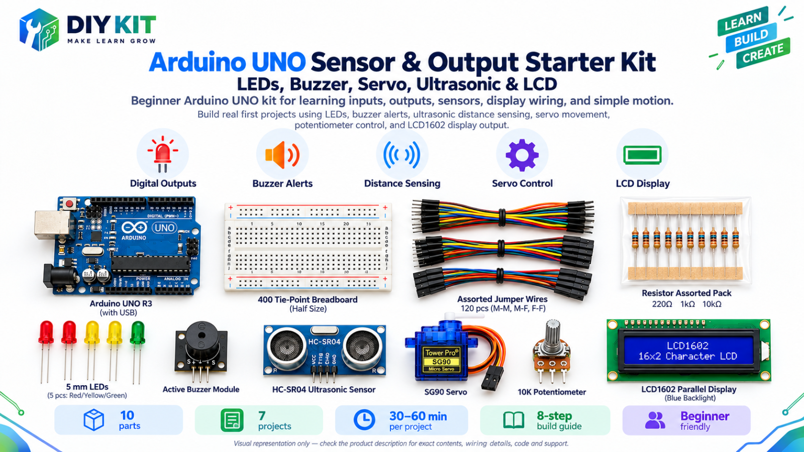
- Media reviewReplace any photo showing a half-size breadboard or implying the optional buzzer is part of the checked main build.
Compiler-check record. The supplied 289-line source was compiled for ESP32 core 3.3.11 in normal and PLANT_DIAGNOSTIC=true modes with Adafruit BME280 2.3.0, BusIO 1.17.4, and Unified Sensor 1.1.15. Compilation confirms source/toolchain compatibility, not physical wiring or sensor performance.
Images are visual representations only. Component appearance, pin order, connector style, and board revision may vary. Always follow labels and specifications on the supplied part.