Overview
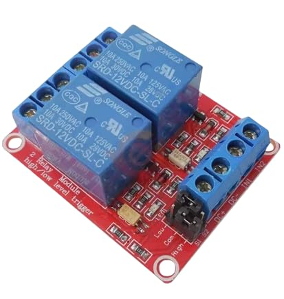
This 2-channel 5V relay module is designed to let microcontrollers and embedded systems switch higher-power AC or DC loads using low-voltage control signals. It is a common interface board for Arduino-compatible controllers, Raspberry Pi, and other MCU platforms where GPIO pins cannot directly drive mains devices, motors, lamps, solenoids, or power supplies. Each channel uses an electromechanical relay to provide galvanic isolation between the control side and the load side, and many module revisions add optocouplers to further improve noise immunity in electrically harsh environments.
Technical Details
The module integrates two independent relay driver channels. A typical channel includes: a logic input stage (often via an optocoupler), a transistor driver to energize the relay coil, a flyback suppression path for coil transients (implementation varies by revision), and status indication LEDs. When the input is asserted (either active-high or active-low depending on the trigger configuration), the driver energizes the 5V relay coil, mechanically changing the contact state from the default (COM to NC) to the energized state (COM to NO).
Optocoupler isolation (when present and correctly wired) helps decouple the controller’s GPIO ground from switching noise generated by inductive loads and relay coil transients. Some versions provide separate JD-VCC/VCC power domains and a jumper link; this can allow the relay coil supply to be isolated from the logic supply. Because board layouts and isolation implementation vary by module revision, confirm whether grounds must be common for your intended wiring method and whether the optocoupler input side is truly isolated.
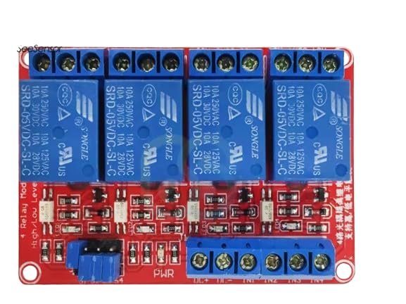
High/Low level trigger capability is often implemented through a jumper, solder bridge, or input conditioning network. In practice, “low-level trigger” means the relay activates when the input is pulled LOW relative to the module logic reference, while “high-level trigger” activates when the input is driven HIGH. Trigger thresholds depend on the optocoupler LED resistor network and driver stage, so for 3.3V controllers you should verify that the module reliably recognizes your GPIO high level and that the input current is within the GPIO’s sourcing/sinking capability.
Specifications
- Channels: 2 relay channels (independent control)
- Relay coil voltage: 5V (module supply for coils)
- Trigger type: High/Low level trigger support (varies by module revision; check board markings/jumpers)
- Input interface: Logic-level IN1/IN2 control pins (exact threshold varies by module revision; check datasheet/markings)
- Isolation: Optocoupler present (as specified); degree of isolation depends on PCB design and power-domain wiring
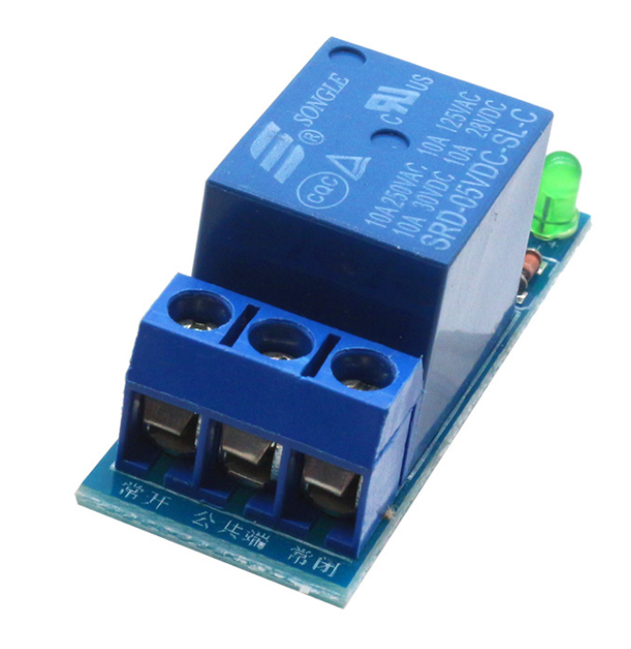
- Output contacts per channel: COM, NO, NC screw terminals
- Load type: AC or DC switching via mechanical relay contacts (within relay contact rating printed on relay case; common variants are 10A class, but verify your unit)
- Indicators: Power/Status LEDs (exact labeling varies by module revision)
- Mounting/connection: Screw terminals for load wiring; pin header interface for control (pin count/order varies by module revision)
Applications
- Home and office automation: switching lights, fans, pumps, heaters (with correct safety practices and ratings verification)
- MCU-controlled power routing: turning external modules or subsystems on/off under firmware control
- Industrial prototyping: isolating PLC/MCU logic from noisy loads using relay contacts
- Test benches: automated cycling of devices under test, power supplies, and fixtures
- Robotics and mechatronics: controlling solenoids, valves, and other actuators (ensure proper snubbers for inductive loads)
Integration Notes
1) Power: Provide a stable 5V supply capable of handling relay coil inrush/current for two channels. USB 5V from a controller board may be insufficient depending on board design and how many relays are energized simultaneously; use an external 5V supply if needed.
2) GPIO drive: Confirm whether the module is active-high or active-low in your configuration. If using a 3.3V MCU, validate reliable triggering and consider using a transistor/driver stage if required.
3) Load wiring: Use COM/NO for normally-off loads (energize relay to turn ON) and COM/NC for normally-on behavior. Tighten screw terminals securely and use appropriately rated wire.
4) Inductive loads: Add proper suppression (RC snubber for AC, flyback diode/TVS for DC loads where applicable) to reduce arcing and EMI, improving relay life and reducing resets/noise.
5) Safety: Mains voltage wiring requires correct insulation, enclosure, strain relief, and adherence to local electrical codes. Keep low-voltage control wiring physically separated from high-voltage conductors.
Included Components
2-Channel 5V Relay Module x1