Overview
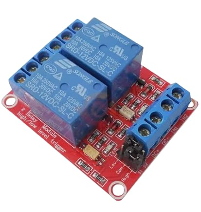
This 2-channel relay module is a compact, Arduino-compatible switching interface designed to let low-voltage controllers safely command higher-voltage or higher-current loads. Each channel uses an electromechanical relay to provide galvanic separation between the control inputs and the switched circuit. The board shown uses two blue Songle-style relays marked SRD-12VDC-SL-C (or equivalent by revision), with a common 10A contact rating printed on the relay case. It is well suited for DIY home automation, test fixtures, lighting control, pump/solenoid switching, and general-purpose power routing where a mechanical relay is preferred.
Technical Details
The module integrates relay driver stages so a microcontroller pin can control the relay without directly powering the coil. Typical designs include a transistor driver (or driver IC), flyback protection for the coil, and indicator LEDs for power/status. Many versions also include optocouplers on the input side to improve noise immunity when switching inductive loads or when the relay supply is electrically “dirty.” Trigger behavior is commonly selectable as HIGH-level or LOW-level trigger using an onboard jumper block; always confirm the silkscreen labels on your specific board revision (often marked “High/Low level trigger”).
Each relay provides three contact terminals: COM (common), NO (normally open), and NC (normally closed). NO closes to COM when the relay is energized; NC opens from COM when energized. This allows you to implement either “power-on when triggered” (NO) or “power-off when triggered” (NC) behavior without changing firmware logic.
Important: This is a 12V relay module, meaning the relay coils require a 12V DC supply to actuate. The control input logic level and isolation behavior can vary by module revision (for example, whether grounds must be shared depends on how the optocoupler and jumper are wired). For best results, check the board’s input header labels and any included datasheet/schematic.
Specifications
- Channels: 2 independent relay channels
- Relay coil voltage: 12V DC (per relay marking)
- Contact rating (per relay marking): up to 10A at 250VAC, 10A at 125VAC, 10A at 30VDC
- Contact type: SPDT per channel (COM, NO, NC)
- Trigger mode: High/Low level trigger selectable (varies by module revision; verify jumper/silkscreen)
- Isolation: Optocoupler present on many revisions (verify component population on your board)
- Input interface: Logic input pins for IN1/IN2 plus power pins (exact pin naming varies by revision)
- Indicators: Power/status LEDs (varies by module revision)
- Termination: Screw terminals for load wiring; pin header for control/power
- PCB form factor: Compact 2-relay module (exact dimensions vary by module revision)
Applications
- Arduino/ESP32/Raspberry Pi GPIO-controlled switching (with proper level/interface considerations)
- Home automation: lights, fans, small pumps, valves, and appliance control within relay ratings
- Robotics and DIY: motor power enable/disable, actuator control, interlocks
- Test benches: automated power cycling, load selection, signal routing (within voltage/current limits)
- Industrial prototyping: PLC-style dry-contact switching and isolation between logic and load circuits
Integration Notes
- Power: Supply the module with a stable 12V DC source capable of driving both relay coils (current draw varies by relay and board design; check datasheet/markings).
- Logic compatibility: Some modules accept 3.3V logic, others are optimized for 5V; trigger thresholds vary by revision. If using 3.3V controllers, validate reliable switching before deployment.
- Grounding/isolation: If the board uses optocouplers, isolation depends on jumper configuration and wiring. In some setups, you may need a common ground; in others, you can keep control and relay power isolated. Follow the PCB labels and schematic if available.
- Load wiring: Use COM/NO/NC correctly for your desired default state. Tighten screw terminals securely and use appropriately rated wire.
- Safety: Mains voltage wiring requires proper insulation, strain relief, fusing, and enclosure. Keep adequate clearance and never touch energized circuits. Do not exceed the relay’s printed ratings, and derate for inductive loads (motors/solenoids) as required.
Included Components
2-Channel 12V Relay Module Board x1