Overview
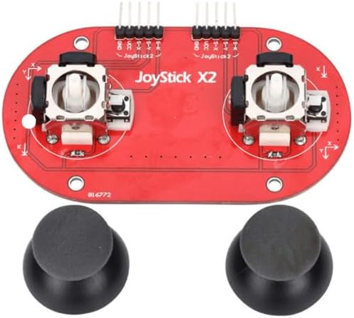
The JoyStick X2 dual analog controller module is a compact input board that combines two independent thumbstick joysticks on a single red PCB. Each joystick is a classic 2-axis analog mechanism designed to output variable voltages for X and Y movement, plus a built-in momentary push switch when the stick is pressed down. This makes it a practical, space-saving solution for DIY game controllers, robotics remote controls, camera pan/tilt rigs, and any project that needs smooth proportional input rather than simple on/off buttons.
Technical Details
Each joystick axis is typically implemented using a potentiometer-based mechanism. As you move the stick, the wiper position changes, producing an analog voltage between GND and VCC on the corresponding VRx/VRy output. Your microcontroller reads these voltages using an ADC channel and converts them into position values. Center position is usually around mid-supply (approximately VCC/2), but exact centering, dead zone, and full-scale range can vary by module revision and joystick tolerance. For best results, perform a quick calibration in firmware: record min/max values for each axis and apply a small deadband around center to prevent drift.
The push-button function (SW) is a momentary tactile switch integrated into each joystick. The SW pin behavior depends on the module design (often active-low when pressed with an internal or external pull-up required). Because implementations can differ, confirm the required pull-up/pull-down using the silkscreen labels and a quick continuity test, or check the seller datasheet if available.
Specifications
- Joystick count: 2 (dual analog sticks on one PCB)
- Axes per joystick: 2 (X and Y)
- Outputs per joystick: VRx (analog), VRy (analog), SW (digital switch)
- Supply voltage (VCC): varies by module revision; commonly used with 3.3V or 5V systems—verify with your controller and module markings
- Analog output range: approximately 0V to VCC (practical range and end-stops vary by joystick tolerance)
- Center output: approximately VCC/2 (may require calibration; drift/dead zone varies by unit)
- Switch type: momentary push-button (electrical behavior varies; often requires pull-up)
- Interface: direct wiring to ADC inputs (VRx/VRy) and GPIO (SW)
- PCB color: Red
- Mounting: PCB includes mounting holes (hole size/spacing varies by module revision)
- Included thumb caps: 2 (one per joystick)
Applications
- Arduino-based RC transmitters and robot controllers (tank steering, differential drive, arm control)
- Pan/tilt camera or sensor gimbal control with proportional speed mapping
- Menu navigation and UI input for DIY handheld devices
- Game controller prototypes and educational electronics labs
- Servo control, motor speed control, and cursor/position input where analog precision is needed
Integration Notes
- Wiring: Connect VCC and GND to your system supply, then connect each VRx/VRy to separate ADC-capable pins. Connect SW to a GPIO pin and enable an internal pull-up/pull-down as required by your module’s switch wiring.
- Calibration: Read center values at startup and apply a deadband to reduce jitter. Map ADC readings to your control output (e.g., -100% to +100% motor command).
- Noise handling: Use simple averaging (moving average) or low-pass filtering in firmware for smoother control, especially with long wires.
- Compatibility: Works best with controllers that have enough ADC channels (4 analog channels total for two joysticks). If your platform lacks analog inputs, you may need an external ADC.
Included Components
1x Dual Analog Joystick X2 Module, 2x Thumb Caps