Overview
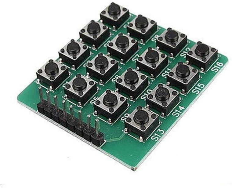
This 4x4 Matrix Keypad Module is a practical input solution when you need multiple buttons without consuming a large number of microcontroller pins. It provides 16 momentary tactile keys arranged as a 4-row by 4-column switch matrix, allowing you to detect any key press using only 8 GPIO lines (4 row lines + 4 column lines). With a PCB size of 68.4mm x 65.5mm, the module is well suited for mounting behind a front panel, integrating into an enclosure, or using directly on a prototype base where a rigid keypad surface is preferred over flexible membrane keypads.
Technical Details
The keypad is implemented as a passive switch matrix. Each button sits at the intersection of one row trace and one column trace. When a key is pressed, it electrically connects its corresponding row and column together. Your microcontroller identifies which key is pressed by scanning:
1) Configure one group of lines (commonly rows) as outputs and the other group (commonly columns) as inputs with pull-ups (internal or external).
2) Drive one row active at a time (for example, pull the row LOW while other rows remain HIGH or high-impedance depending on your method).
3) Read the column inputs; any column that changes state indicates a pressed key at the intersection of the active row and that column.
4) Repeat for each row at a steady scan rate.
Because mechanical switches bounce, reliable detection typically requires debouncing in firmware. This can be done by time-based filtering (e.g., require a stable state for 10–50 ms), state-machine debouncing, or library-based debouncing. For user interfaces, scanning at a few hundred Hz is common, but your optimal scan rate depends on your MCU speed, power goals, and how you handle debounce and key repeat.
Matrix keypads can also exhibit “ghosting” in certain multi-key press combinations if the matrix does not include per-key diodes. Many 4x4 tactile matrix modules are diode-less, meaning they are best used for single-key input or controlled multi-key scenarios. If your application requires accurate detection of multiple simultaneous key presses, confirm whether your specific module revision includes isolation diodes, or implement software constraints (e.g., accept only one key at a time).
Specifications
- Key layout: 4 rows x 4 columns (16 total keys)
- Electrical interface: passive switch matrix (no onboard controller)
- Required MCU pins: 8 GPIO (4 row + 4 column)
- Logic compatibility: suitable for 3.3V and 5V microcontrollers (used as digital inputs/outputs; exact pull-up method depends on MCU)
- PCB dimensions: 68.4mm x 65.5mm
- Switch type: momentary tactile push buttons (exact feel/actuation varies by module revision)
- Connector/pinout: typically 8-pin row/column header or pads; labeling/order varies by module revision—verify with continuity test or documentation
- Debounce: handled in firmware (library or custom code); no dedicated hardware debounce specified
Applications
- Arduino keypad input for menus, parameter entry, and device configuration
- DIY access control prototypes (PIN entry), electronic locks, and control panels
- Robotics and automation projects requiring a compact local user interface
- Test jigs, calibration tools, and bench instruments needing quick numeric input
- Microcontroller learning projects demonstrating GPIO scanning and debouncing
Integration Notes
- Identify row/column mapping before coding: module silkscreen and pin order can differ by revision. A quick continuity test (multimeter) can confirm which pin corresponds to each row/column.
- Use internal pull-ups (if available) on the input side to simplify wiring; otherwise add external pull-up resistors as needed for stable readings.
- Keep wiring short or use twisted pairs/ground reference in noisy environments to reduce false triggers.
- If you experience intermittent presses, increase debounce time, reduce scan speed slightly, and ensure solid ground reference between keypad and MCU.
- For enclosure mounting, align the PCB so the tactile buttons meet the panel openings cleanly; avoid mechanical stress on the PCB when tightening mounts.
Included Components
1x 4x4 Matrix Keypad Module (16-Key), 68.4mm x 65.5mm PCB