Overview
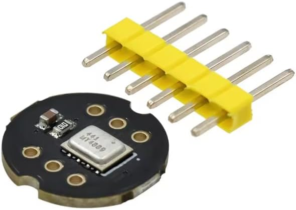
This omnidirectional microphone module PCB is designed to make capturing environmental audio simple in embedded projects such as ESP32-based voice triggers, Arduino sound-reactive builds, and Raspberry Pi sensor experiments. The board integrates a microphone capsule and supporting analog front-end circuitry to produce an analog signal that can be sampled by a microcontroller ADC or fed into additional audio processing stages. The omnidirectional pickup pattern helps it capture sound from all directions, making it well-suited for general room audio sensing, noise monitoring prototypes, and interactive installations.
Technical Details
The module is built around an electret-style microphone capsule (commonly used in compact sensor boards) paired with an onboard preamplifier/bias network. In typical designs, the microphone requires a bias current and produces a small AC signal riding on a DC bias level. The onboard circuitry conditions this signal so it can be measured by an ADC input. Because different production runs may use different amplifier ICs/transistor stages and resistor values, key parameters such as gain, output bias point, and maximum output swing can vary by module revision. For best results, confirm the output behavior with a multimeter/oscilloscope and adjust your firmware sampling method accordingly (for example, sampling around the DC midpoint and calculating peak-to-peak or RMS).
When interfacing with ESP32, note that ESP32 ADC inputs measure voltage relative to ground and typically expect signals within the ADC input range configured in firmware. Since microphone outputs are usually biased above ground, you should read the ADC continuously and remove the DC offset in software (high-pass filtering or subtracting the running average) to extract the audio waveform or sound level. If your application needs stable sound level detection rather than full audio, you can compute envelope/energy over a window and apply thresholds with hysteresis to reduce false triggers.
Specifications
- Microphone type: Omnidirectional microphone capsule (electret-style typical; exact capsule varies by module revision)
- Output type: Analog audio output (AC signal with DC bias; exact bias level varies by module revision)
- Supply voltage: Compatible with 3.3V and 5V systems (exact operating range varies by module revision; verify before use)
- Interface: Solder pads / through-hole header connection (pinout varies by board revision; check silkscreen)
- Signal conditioning: Onboard preamp/bias network (gain and bandwidth vary by module revision)
- PCB: Compact round/irregular sensor PCB as shown; mounting holes/pads present (exact dimensions vary by module revision)
- Recommended verification: Check pin labels, measure VCC/GND continuity, and confirm output idle bias before connecting to ADC
Applications
- ESP32 sound level sensing and voice activity detection (VAD-style thresholding)
- Arduino clap switch, knock detection, and audio-reactive lighting
- Raspberry Pi analog front-end experiments (with external ADC)
- Noise monitoring prototypes, classroom STEM audio labs, interactive art installations
- Trigger input for automation (sound threshold -> relay/LED/buzzer logic)
Integration Notes
1) Power: Connect VCC and GND according to the board silkscreen. If using 3.3V MCUs, start with 3.3V supply unless your specific module revision specifies otherwise.
2) Output to ADC: Connect the analog output to an ADC-capable pin. Expect a DC-biased signal; do not assume it is centered at 0V.
3) Firmware: Sample at an appropriate rate for your goal (low rate for level detection, higher for waveform analysis). Remove DC offset in software and compute amplitude/energy.
4) Noise/grounding: Keep analog wiring short, use a solid ground reference, and avoid routing near high-current switching lines (motors, DC-DC converters).
5) Calibration: Because gain varies by revision, calibrate thresholds in your environment and consider adding averaging/hysteresis to prevent chatter.
Included Components
Microphone module PCB, pin header strip