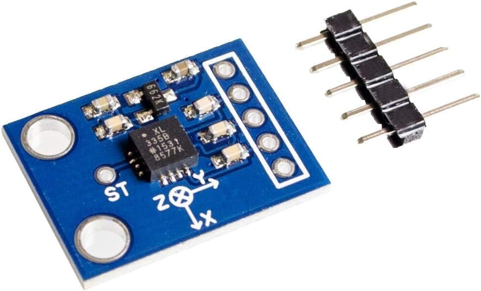
The GY-61 ADXL335 3-Axis Accelerometer Module is an easy-to-use motion sensor board that measures acceleration on three axes (X, Y, Z) using the well-known ADXL335 analog MEMS accelerometer. It outputs three analog voltages proportional to acceleration, allowing you to detect tilt, movement, vibration, and orientation changes in real time.
Because it’s an analog-output accelerometer, the GY-61 is great for beginners and projects where you want straightforward ADC readings without I2C/SPI configuration. It’s commonly used in DIY robotics, self-balancing experiments (basic), gesture/tilt control, vibration monitoring, and educational physics demonstrations.
How It Works
The ADXL335 senses acceleration along each axis and outputs a corresponding analog voltage:
- XOUT → acceleration on X axis
- YOUT → acceleration on Y axis
- ZOUT → acceleration on Z axis
At rest, you can use the readings to estimate tilt relative to gravity. During motion, the outputs change based on acceleration and vibration.
Key Features & Benefits
- 3-Axis Sensing: Detect motion and tilt in X/Y/Z directions
- Analog Output: Simple interface—just read voltages using ADC inputs
- ±3g Measurement Range: Suitable for general motion, tilt, and vibration projects
- Compact Module: Easy to mount on robots and prototypes
- Wide Compatibility: Works well with Arduino and many MCU boards with ADC pins
- Great for Learning: Useful for STEM experiments and sensor calibration practice
Pinout (Typical GY-61 Module)
| Pin | Function |
|---|
| VCC | Power input |
| GND | Ground |
| X | X-axis analog output |
| Y | Y-axis analog output |
| Z | Z-axis analog output |
| ST | Self-test (if provided on the board) |
Note: Many ADXL335 modules are best operated at 3.3V. Some breakouts include regulation allowing 5V input, but the sensor itself is a low-voltage device. If unsure, power at 3.3V and keep outputs within ADC limits.
Typical Specifications
| Item | Typical Value |
|---|
| Sensor | ADXL335 |
| Axes | 3 (X, Y, Z) |
| Output | Analog voltages (X/Y/Z) |
| Measurement Range | ±3g |
| Operating Voltage (Sensor IC) | ~1.8V–3.6V (3.3V typical) |
| Common Use | Tilt, acceleration, vibration sensing |
Common Applications
- Tilt-controlled robotics and RC projects
- Motion/vibration monitoring and alarms
- Balance detection and orientation experiments
- Educational physics projects (acceleration/gravity)
- DIY input devices (gesture/tilt controllers)







![Temperature sensor [TMP36]](https://diykit.ae/uploads/products/1783496467_29c5e5faceee15fbbda9-w320.webp)


